Making the Makestra
Repurposed, bio-electronic and 3D-printed instruments
Makestra is a project that explores the use of an alternative tuning system and materials to create a DIY ensemble of non-traditional instruments. The project seeks to reduce the complexities involved with learning music and to expand on alternative methods of musical expression. Current instruments in the ensemble include 3D-printed flutes, the Hydrowoofer, a 16-tone piano and a Playable Plant.
Principles and Concepts of the Makestra
The Makestra is a new experimental DIY project developed using various elements of modern technology to create a series of instruments from scratch to form a large, informal ensemble. The Makestra currently consists of a 15-strong 3D-printed flute ensemble, a 16-tone acoustic/electric piano, the Hydrowoofer (a subwoofer filled with water) and a touch-responsive Playable Plant. Planned future instrumental developments include water-based percussion and alternatively tuned string instruments.
All the instruments featured in the Makestra — the 16-tone piano, 3D-printed flutes, the Hydrowoofer and the Playable Plant — have been made by the authors. One of the reasons for this DIY approach is that it allows the authors to explore music and harmony at a more grassroots level, allowing the authors to experience the act of music as both instrument creator and player.
The Makestra instruments are based on a foundation of knowledge sharing, which is a keystone in DIY communities. For instance, the whistle design for the 3D-printed flutes was based on an existing open source whistle design, while the inspiration behind the Playable Plant was found on the Makey Makey website, where multiple designers have shared different iterations of the concept. Makestra was also made in the Perth Artifactory, a maker space where participants can share tools and knowledge in a collaborative workspace.
Makestra intends to continue in this vein of collaboration by being a platform for making explorations with musical expression and interfaces accessible to a broader audience. Through allowing audiences to interact with these instruments and sharing the methods, Makestra hopes to encourage more experimentation and critical engagement with new technology. Makestra also intends to demonstrate that interfaces can be built using a combination of disposable technology and bricolage.
Hearing Mathematics: A 16-Tone Alternative Tuning Method
Another element of the Makestra is the development of an alternative tuning method, which is used to tune the Makestra instruments. This system links colour with frequencies as a method of understanding and communicating the tuning system, and as a basis for an alternative scoring method. This alternative tuning system is also an exploration of moving away from equal temperament.
Equal temperament allows multiple instruments to play in harmony and allows access to 12 tonal centres with relative ease. Every equivalent interval (e.g., a major third, a minor seventh) within equal temperament is “equal”, regardless of the note it is calculated from (i.e. C-E and F-A are both “equal” major thirds). For this to occur with a twelve-tone musical system, the natural intervals (aside from octaves) are all slightly out of tune (Halewood 2015) in relation to the harmonic series.
The alternative proposed by Makestra is a 16-tone tuning system based on harmonic tuning. Harmonic tuning gives an exact numerical figure to every note and also gives access to a variety of exact ratios that are used as the basis for consonance and dissonance. The construction of the orchestra exploits the possibilities offered by MIDI and software for greater flexibility and consistency in defining exact pitches. The incorporation of an alternate tuning system helps the orchestra achieve the goal of creating new textures and expanding the potential of artistic expression.
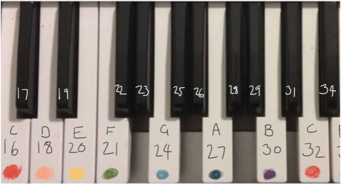
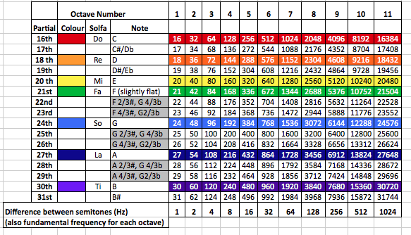
The 16-tone tuning system used in the Makestra is related to just intonation, where the pitches of the individual notes correspond to frequency relationships found within the harmonic series. Figure 1 shows an overview of the frequency spectrum used in the system. In this system, colours are used as a method of conveying musical information, in particular where the frequencies correspond to equal temperament. The colours are translated to correspond to the white keys on an alternative piano keyboard design (Fig. 2).
Developing the 16-Tone System
The lowest octave of this 16-tone tuning system starts at 16 Hz (the 16th partial of 1 Hz) and extends to 31 Hz (31st partial). For each ascending octave, the pitches of the previous 16 tones are doubled (i.e. the second octave spans from 32–62 Hz, the third from 64–124, and so on).

Assigning exact numerical relationships to tones and their intervals can make responding to notes a simpler process. Visual processing can be calibrated to frequency without the need to account for decimal places. Because the consonant tones found in this system are not considered “slightly out of tune” (as with equal temperament), it may be more likely for relative harmonics to be visually represented as having a tangible connection to a fundamental frequency.
Consonance and dissonance can then be viewed as more of a spectrum, as opposed to extremes. Certain intervals are close to being perfectly consonant, but by using rational numbers we can quantify consonance and dissonance precisely. For example, the interval F-C in equal temperament is a “perfect fifth”. Using the 16-tone tuning method, the lowest F on the instrument can be labelled “21” (its value in Hertz) and the C above it can be labelled “32”, i.e. a relation of 32/21, or 1.5238. This is an interval that is slightly larger than a perfect fifth, which may serve a harmonic function in the future.
Makestra Instruments
The 16-Tone Piano
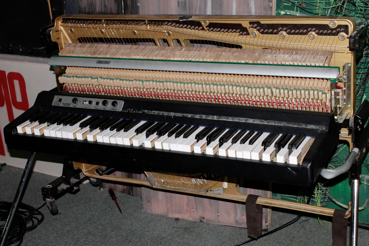
The piano used in the Makestra (Fig. 3) is based on the 16-tone tuning system described above, and was made by converting a Kawai EP-608 electric piano. This model has a full hammer and string mechanism, along with electric pick-ups. One of the advantages of re-purposing this particular model was that it featured straight piano keys. On grand pianos, for example, every key is made specifically for its individual position along the key bed. While the visible part of the key is straight, the extension of each key inside the piano (beyond the playing surface, normally hidden from view) is cut at a different angle. Although on this model the entire key is straight, transposing (repurposing) the keys is nonetheless not straightforward, as the positioning of the individual key pins (installed underneath each key to ensure the vertical action of the keys remains stable and consistent) needs to be shifted to accommodate different keys. We chose to manufacture some of the keys ourselves, with standardized key pin positioning to allow for simpler fabrication and transposition.
Additionally, each key of the Kawai has only a single string (mid and upper ranges normally have two or three strings per key). This meant that there was less overall tension on the piano frame (in comparison with the majority of pianos), which reduced the complexities required to calculate the appropriate tension for the frame to resonate to specific frequencies (Fig. 4).
The process of altering the electric stringed piano was as follows:
- Calculate the reorientation of keys to allow for minimum strain on the piano frame;
- Fabricating replica black and white keys (for a 16-tone instead of 12-tone octave);
- Reposition the key pins;
- Source, resize and rearrange the piano strings to suit the new tuning;
- Tune the piano.
The piano keys were designed using CAD software. The core structure of a single key is made up of three slices that were cut with a laser cutter and glued together. This process allowed for consistent accuracy in production, which is necessary when making piano keys that needed to sit adjacent to each other and move independently.

Reorienting the piano keys was a compromise between allowing for sufficient bass and acknowledging that the string lengths towards the top will need to tune and resonate at lower pitches. The alternative tuning system also has a wider octave than the original — three octaves in the alternative tuning occupy the physical space of four octaves in equal temperament. To accommodate this, the original bottom octave of strings was removed. The second octave was moved to the bass and strings were spaced out to retain their calibration between length and required frequency.
Missing strings were sourced from an old upright piano and were cut to length and fastened with cable crimps. The upper strings are the original strings that came with the Kawai, but have been detuned to match the intended tuning.
3D-Printed Flutes

The 3D-printed flutes are the result of incorporating cutting-edge modern technology, basic music theory, performance practice and experimental music. The initial idea was inspired by the work of Kraig Grady at the University of Wollongong (Ritz et al. 2015). Grady’s work has been focussed around modelling the frequency response of CAD-designed 3D shapes to produce microtonal flutes that respond consistently and accurately. For the Makestra 3D-printed flute ensemble, a similar approach was taken, but the 3D printing was used for the mouthpiece production only.
The pipe length of flutes was made from PVC conduit pipe, which is both inexpensive and consistent in its physical dimensions. Reducing the amount of material to print also greatly reduces print time and means that more flutes can be constructed simultaneously.
Creating a 3D-printed Flute
The steps taken to build the Makestra’s flutes were as follows:
- Examine and measure existing flutes to determine general length and hole structure;
- Create a 3D model of a whistle using AutoCAD;
- Print a 3D model using a 3D printer;
- Clean the printed whistle to smooth out irregularities;
- Colour the flutes according to their fundamental frequencies.
In our initial attempts we attempted to print an entire replica flute. This method allowed for full customisation of the shape and diameter of the resonant chamber, as well as accurate replication for each reprint. However, 3D printers can be temperamental to calibrate, and produce inconsistent results as the weather changes. Larger print jobs can mean a significantly longer print time, with one flute potentially taking several hours.
Three flute sizes were selected with the aim of exploring harmonic tuning. Each size was coloured to reflect the relationship to the harmonic tuning used in the Makestra (Fig. 5). The central flute (red) had its fundamental tone pitched at 512 Hz. Ascending tones from the fundamental follow the same logic as the pentatonic scale.
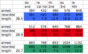
The other two flutes (green and blue) used identical frequency ratios, but their fundamentals were pitched a perfect 4th (4/3) above and below the red flute, respectively. This makes the green fundamental 683.66 Hz and the blue fundamental 384 Hz (Fig. 6). Initially the preferred relationship between these flutes had been a perfect fifth (3/2), but this resulted in the green and blue flute lengths to be impractically short and long, respectively.
Fine-tuning the eventual flute lengths was done through trial and error. To determine the length of the flutes, a piece of 50 cm conduit pipe was marked in 2 cm intervals. Starting from its original length, the pipe was then trimmed to the first mark and its frequency recorded. The process was repeated, and through this method a frequency response curve was plotted. Once the desired lengths of the individual flutes were established, the same process was repeated to determine where the holes should be for each respective pipe length. There were many attempts to calibrate the hole positions, as the position and size of one hole on a pipe can sometimes affect the frequency response of other holes in the same pipe.
Hydrowoofer
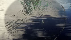
The genesis of the Hydrowoofer stems from a previous set of works entitled Seeing Sound, where continuous droplets of water were recorded through a microphone and video camera. Three coloured lights were used as sources of illumination, and the video camera projected the patterns these droplets made on the surface of the water onto a screen. The Hydrowoofer now incorporates a sound-responsive light ring and direct audio input, as well as a camera to capture the vibrations of the water as the speaker plays.
The Hydrowoofer is based on the principle of cymatics, which refers to the visualisation of sound through a physical medium. An analogy can be made with the response of the human eardrum, as both phenomena exist at a membrane where sound converts from one form of energy to another. Cymatics is explored through various media, where sound energy is transferred through solid or liquid state materials. An early demonstration of this was the Chladni plate, where Chladni drew a violin bow against the edge of a horizontal metal plate covered in salt (UCLA Physics & Astronomy Lab).
The Hydrowoofer was made using the following steps:
- Source a large, water-resistant passive speaker — the ideal option was polyurethane-coated speakers;
- Fabricate a simple enclosure (cube with a hole for the speaker) to protect the electronics from water and to contain the speaker, made from 9 mm clear acrylic and cut using table and laser saws;
- Wire the cables to the subwoofer;
- Seal every joint with liquid silicone or a suitable adhesive for the enclosure material in order to prevent water from leaking;
- Connect the NeoPixel Ring to an Arduino (the NeoPixel Ring also serves to illuminate the surface of the water, making patterns formed from vibrations more visible);
- Acquire, combine and modify the Arduino code to trigger coloured sequences from the NeoPixel Ring;
- Place a camera on a stand above the speaker and project the image onto a screen for audiences to view.
The first version of the Hydrowoofer was a speaker housed inside an enclosure made of 3 mm MDF, with some vents to allow cooling. A hinged door was fitted on the side to allow access to the amplifier controls. While this enclosure was able to stabilize the speaker, some flaws became apparent. One issue was the material — 3 mm MDF was too thin to be able to prevent the speaker from vibrating. Another issue with this initial design was the lack of sealing — despite being covered by PVA glue, water leaked into the enclosure and turned the Hydrowoofer into an electrical hazard. Despite the presence of vents, the enclosure was noticeably hot and the temperature risked burning out the amplifier.
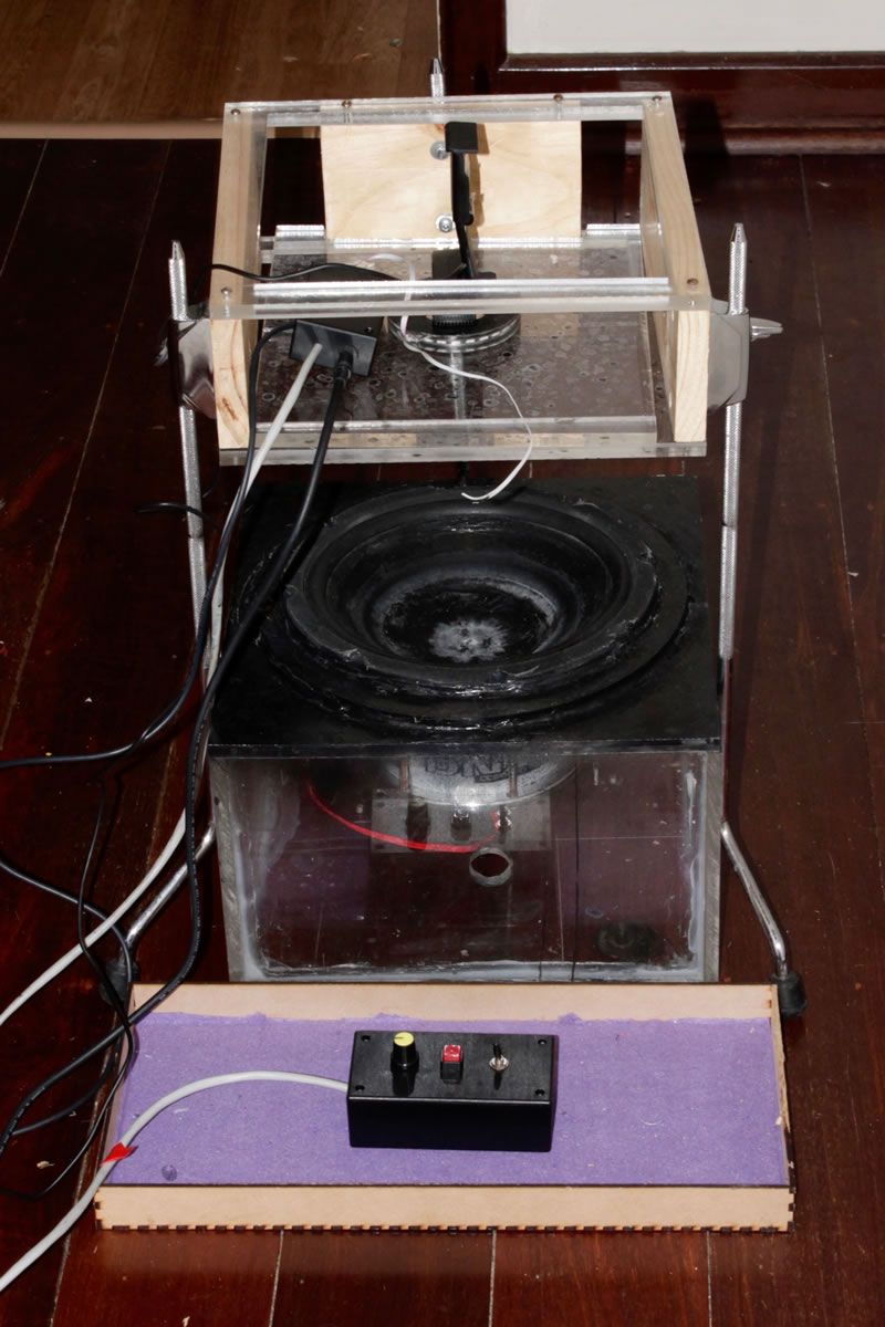
The current version of the enclosure (Fig. 7) separates the amplifier from the subwoofer, thus removing the potential for equipment damage, personal injury or overheating issues. The speaker used in the current version of the Hydrowoofer is a taken from a car stereo system.
The NeoPixel Ring, manufactured by Adafruit, is used as source of illumination for the vibrating surface of the water held in the Hydrowoofer during operation (Fig. 8). Each of the 24 LEDs in the NeoPixel Ring is individually addressable. By connecting the ring to an Arduino, the colour and brightness of each LED can be controlled using a single data cable. Adafruit also provides Arduino libraries and the Hydrowoofer currently runs a modified version of the Strandtest library sketch in combination with an open-source colour organ code. The Strandtest library sketch allows the NeoPixel Ring to play sequences of colours and animation, while the colour organ code controls the LED lights by metering the volume of audio signals.
The NeoPixel Ring also features the following electrical components (Fig. 9):
- A pot as a brightness control;
- Switch for power;
- DC power in;
- Headphones jack in.
One of the challenges encountered during the construction of the Hydrowoofer was to make a compact circuit that would fit within the narrow confines of the enclosure. One attempt at making a compact circuit was made by extracting a microchip from a base Arduino board and then resoldering the board with only the necessarily components to make a smaller chip. Unfortunately, there were issues with loading the colour organ code onto this board and the board was only outputting noise.
A second attempt at making a compact circuit involved using an Arduino Mini. This circuit was able to scale the voltage from the audio to a value between 0 and 5 V, which allowed the colour organ code to run. The current version of the NeoPixel Ring responds to audio that is connected to the ring via line out.
The Hydrowoofer will be presented as part of the Seeing Sound audiovisual installation at the Kaleidoscope Festival held in Joondalup, Western Australia in November 2016. Seeing Sound features a series of field footage taken from the Joondalup area and projected onto the screen. A looping soundscape created from field recordings and data elements taken from field footage will be played in the background, and festivalgoers can interact with the soundscape by playing with a MIDI controller. The Hydrowoofer will react to the MIDI controller and its responses will be projected and overlaid on top of the field footage.
The Playable Plant
Another method of creating instruments for the Makestra was explored with the use of simple, inexpensive technology such as the Makey Makey, which facilitates the creation of nature-based interfaces as the basis for instruments. One example is using the Makey Makey Classic in conjunction with living plants to make touch-based instruments, as a way to explore methods of interactivity and as a demonstration of how non-traditional material can be used as a method of sonification.
The Makey Makey Classic is a circuit board and key replacer, which allows creators the ability to re-map keys (i.e. WASD, arrow buttons, space bar) and mouse buttons (i.e. left and right click). The Makey Makey Classic works with open and closed circuits, with conductive materials used to control the opening and closing of the circuits.
One of the advantages of using the Makey Makey is that enables people from non-technical backgrounds to make nature-based interfaces (Beginner’s Mind and Shaw 2012). It requires no programming or assembling electronics from users and is compatible with a variety of software. The Makey Makey is also based on the Human Interface Device (HID) protocol, whereby the human body becomes part of the interface. Following this principle, any item that has conductive properties — such as plants, fruit and water — can be used as part of an interface. The Makey Makey encourages the combining of physical and digital bricolage — that is, the creation of physical interfaces out of everyday objects.
The basic steps of making a playable plant are:
- Connect the Makey Makey to a computer or laptop;
- Select a sound file on the laptop (or alternatively link the Makey Makey to a digital work station) that can be triggered with a key or mouse click;
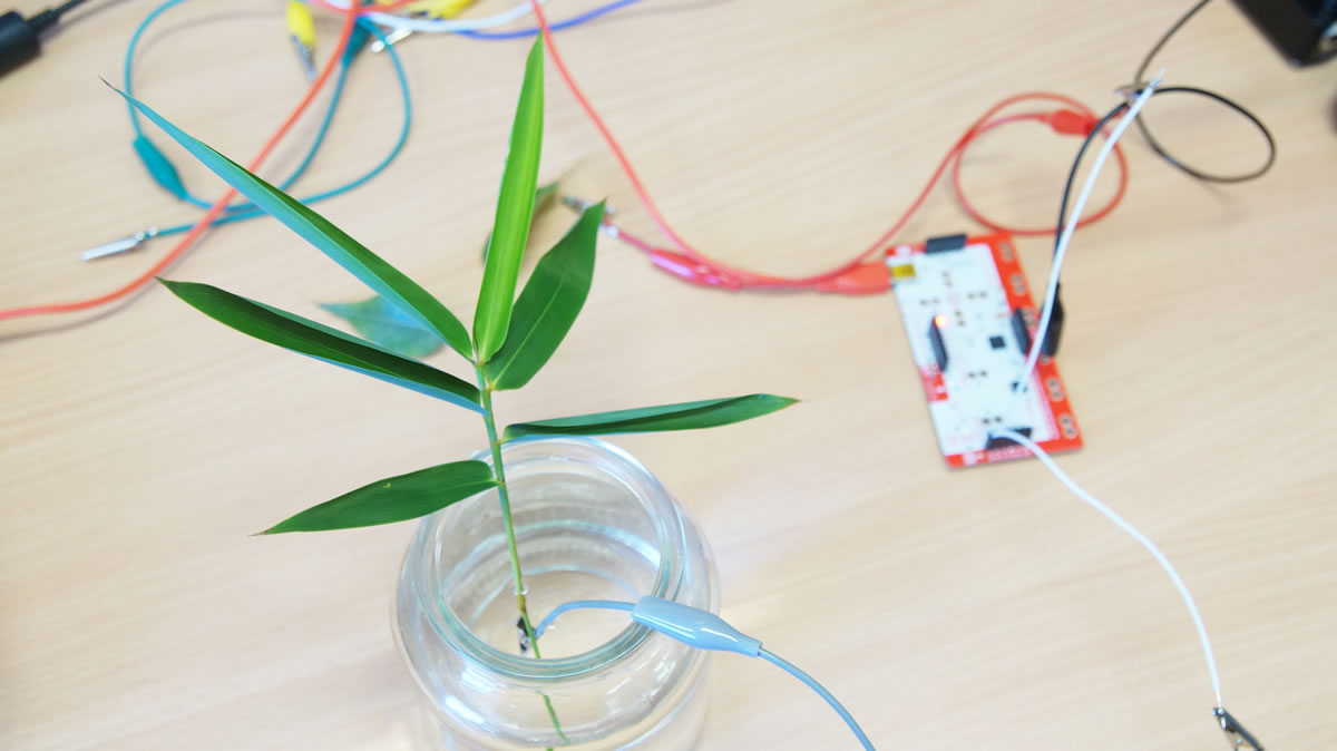
- Find a plant and place it into a jar of water;
- Place one end of an alligator clip into the water;
- Connect the other end of the alligator clip to a module on the Makey Makey;
- Connect one end of a second alligator clip to the ground on the Makey Makey and connect the other end to the user’s body.
The ability to select which sound file(s) that a Makey Makey triggers, coupled with its simple setup, allows artists to customize mappings that are specific to pieces.
For Makestra, the Playable Plant acts as a playful commentary of how current technology can be used to create interfaces. It also encourages thinking outside conventions regarding interfaces by expanding on possibilities regarding materials and arrangements. Within the ensemble, the Playable Plant will be used for percussion and sound effects, and to offer aural and visual support for the harmonic instruments.
The repertoire of the Playable Plant can also be extended by mapping the controller to specific functions of a digital audio workstation. For instance, the Playable Plant can be used to trigger specific sequences of loops or to play notes from a MIDI keyboard.
There are some issues with Playable Plant. Firstly, the responsiveness of the Makey Makey can vary depending on where a person touches a plant, and generally there is a delay between the initial touch and response. Secondly, in order for the circuit to be operational, the ground clip must also be connected to the performer, which creates restrictions on movement. The Makey Makey is limited to six keys, which restricts the number of simultaneous inputs on one instrument.
In our experiences using the Playable Plant in the Makestra, it has been best suited for triggering loops and incidental effects (such as pre-recorded environmental sounds), where precise timing is not crucial to the piece.
Acknowledgements
Acknowledgements go to the Composition department at the Western Australian Academy of Performing Arts. Dr. Stuart James, Dr. Lindsay Vickery and Associate Professor Cat Hope have been influential in their development and delivery of the composition course that has inspired and supported many elements of the Makestra. Acknowledgements also go to the Perth Artifactory. All of the instruments in the Makestra were produced within the Artifactory with the advice and support of many talented members. The Artifactory reinforced a sense of DIY that empowered the production of the musical instruments described above.
Bibliography
Beginner’s Mind Collective and David Shaw. “Makey Makey: Improvising tangible and nature-based user interfaces.” TEI ’12. Proceedings of the 6th International Conference on Tangible, Embedded and Embodied Interaction (Kingston ON, Canada: Queen's Human Media Lab, 19–22 February 2012), pp. 367–370.
Golsteijn, Connie, Elise van den Hoven, David Frohlich and Abigail Sellen. “Hybrid Crafting: Towards an integrated practice of crafting with physical and digital components.” Personal and Ubiquitous Computing 18/3 (March 2014), pp. 593–611.
Halewood, Michael. “On Equal Temperament: Tuning, modernity and compromise.” History of the Human Sciences 28/3 (July 2015), pp. 3–21.
Ritz, Christian, Matthew Dabin, Terumi Narushima, Kraig Grady and Stephen Beirne. “Optical Design & Engineering”. http://spie.org/newsroom/6082-3d-printing-for-custom-design-and-manufacture-of-microtonal-flutes [Last accessed 7 November 2016]
Silver, Jay and Eric Rosenbaum. Makey Makey. Website. http://makeymakey.com
Tanenbaum, Joshua G., Amanda M. Williams, Audrey Desjardins and Karen Tanenbaum. “Democratizing Technology: Pleasure, utility and expressiveness in DIY and maker practice.” CHI ’13: “Changing Perspectives”. Proceedings of the 2013 SIGCHI Conference on Human Factors in Computing Systems. (Paris, France, 27 April – 2 May 2013). http://chi2013.acm.org
UCLA Physics & Astronomy Lab. “60. Chladni Plate.” UCLA Physics & Astronomy, Instructional Resource Lab. [n.d.]. http://demoweb.physics.ucla.edu/content/60-chladni-plate [Last accessed 4 September 2016]
Social top