Sound Synthesizer Creates New Musical Effects
This text by Harald Bode describes the capabilities of his 1960 Sound Synthesizer and was published in Electronics magazine on December 1, 1961, a magazine geared toward professionals working in the field of electronics. Of note is Harald’s use of the term “control voltage”, also he mentions “compiling any desired modular configuration”, which indicates Harald saw his synthesizer as an expandable system. The photos and original Harald Bode hand-drawn illustrations are from the Harald Bode Archive.
— Rebekkah Palov, 28 March 2011.
New sounds and musical effects can be created either by synthesizing acoustical phenomena, by processing natural or artificial (usually electronically generated) sounds, or by applying both methods. Processing acoustical phenomena often results in substantial deviations from the original.
Production of new sounds or musical effects can be made either by intermediate or immediate processing methods. Some methods of intermediate processing may include punched tapes for control of the parameters of a sound synthesizer, and may also include such tape recording procedures as reversal, pitch-through-speed changes, editing and dubbing.
Because of the time differential between production and performance when using the intermediate process, the composer-performer cannot immediately hear or judge his performance, therefore corrections can be made only after some lapse of time. Immediate processing techniques present no such problems.
Methods of immediate processing include spectrum and envelope shaping, change of pitch, change of overtone structure including modification from harmonic to nonharmonic overtone relations, application of periodic modulation effects, reverberation, echo and other repetition phenomena.
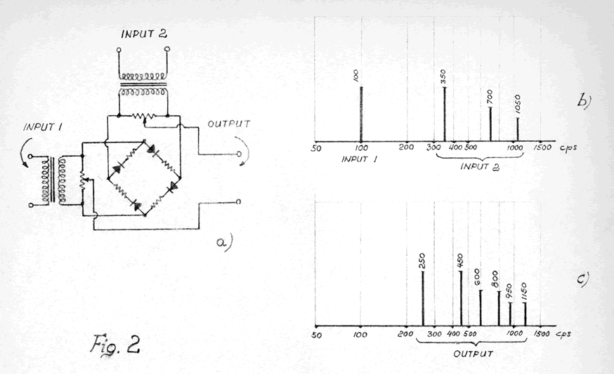
The output of the ring-bridge modulator shown in Figure 2a yields the sum and differences of the frequencies applied to its two inputs but contains neither input frequency. This feature has been used to create new sounds and effects. Figure 2b shows a tone applied to input 1 and a group of harmonically related frequencies applied to input 2. The output spectrum is shown in Figure 2c.
Due to operation of the ring-bridge modulator, the output frequencies are no longer harmonically related to each other. If a group of properly related frequencies were applied to both inputs and a percussive-type envelope were applied to the output signal, a bell-like tone would be produced.
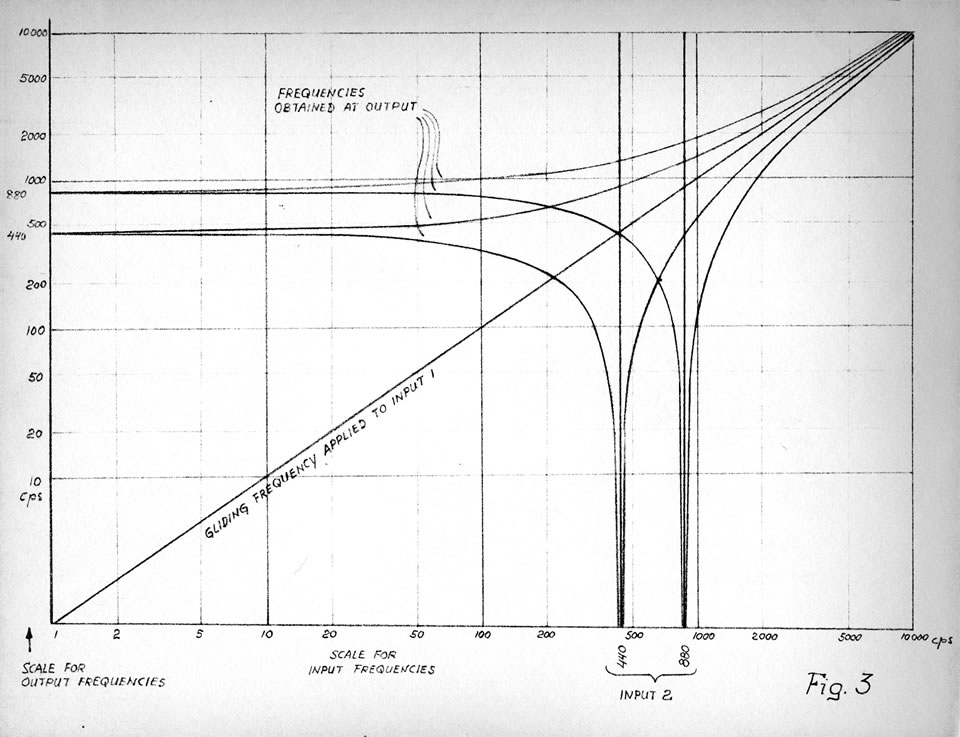
In a more general presentation, the curves of Figure 3 show the variety of tone spectra that may be derived with a gliding frequency between 1 cps 1[1. Ed.: Although in the 1960s the standard for indicating frequency was changed from cycles per second (cps) to hertz (Hz), Harald’s original text has been kept here as he wrote it, in order to maintain the correspondence with some of his figures.] and 10 kcps applied to one and two fixed 440 and 880 cps frequencies (in octave relationship) applied to the other input of the ring-bridge modulator. The output frequencies are identified on the graph.
Frequencies applied to the ring-bridge modulator inputs are not limited to the audio range. Application of a subsonic frequency to one input will periodically modulate a frequency applied to the other. Application of white noise to one input and a single audio frequency to the other input will yield tuned noise at the output. Application of a percussive envelope to one input simultaneously with a steady tone at the other input will result in a percussive-type output that will have the characteristics of the steady tone modulated by the percussive envelope.
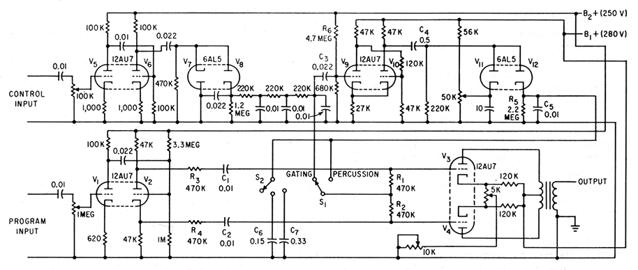
The unit shown in Figure 4 provides congruent envelope shaping as well as the coincident percussive envelope shaping of the program material. One input accepts the control signal while the other input accepts the material to be subjected to envelope shaping. The processed audio appears at the output of the gating circuit.
To derive control voltages for the gating functions, the audio at the control input is amplified, rectified and applied to a low-pass filter. Thus, a relatively ripple-free variable DC bias will actuate the variable gain, push-pull amplifier gate. When switch S1 is in the gating position, the envelope of the control signal shapes that of the program material.
To prevent the delay caused by C1 and C2 on fast-changing control voltages, and to eliminate asymmetry caused by the different output impedances at the plate and cathode of V2, relatively high-value resistors R3 and R4 are inserted between phase inverter V2 and the push-pull output of the gate circuit. These resistors are of the same order of magnitude as biasing resistors R1 and R2 to secure a balance between the control DC signal and the audio portion of the program material.
The input circuits of V5 and V6 act as a high-pass filter. The cutoff frequency of these filters exceeds that of the ripple filter by such an amount that no disturbing audio frequency from the control input will feed through to the gate. This is important for clean operation of the percussive envelope circuit. The pulses that initiate the percussive envelopes are generated by Schmitt trigger V9 and V10. Positive-going output pulses charge C5 (or C5 plus C6 or C7 chosen by S2) with the discharge through R5. The time constant depends on the position of S2.
To make the trigger circuit respond to the beginning of a signal as well as to signal growth, differentiator C3 and R6 plus R7 is used at the input of V9. The response to signal growth is especially useful in causing the system to yield to a crescendo in a music passage or to instants of accentuation in the flow of speech frequencies.
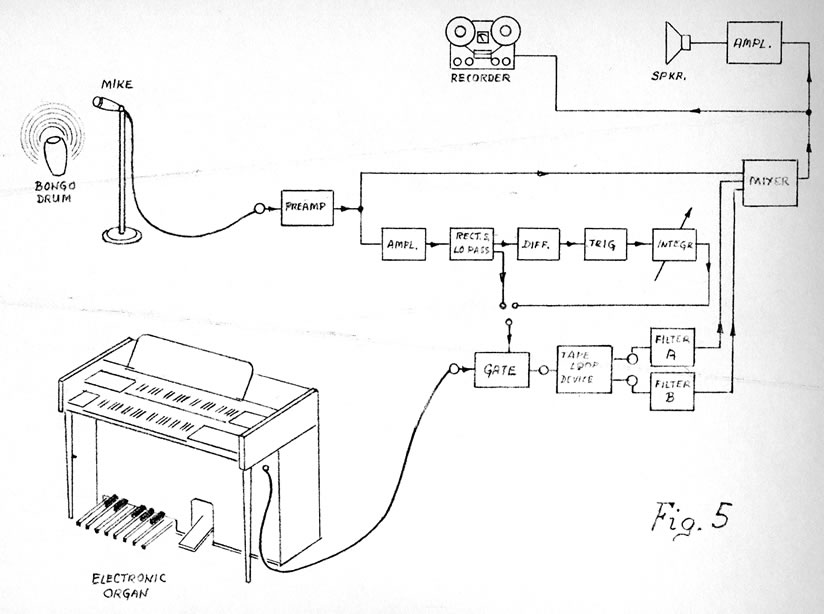
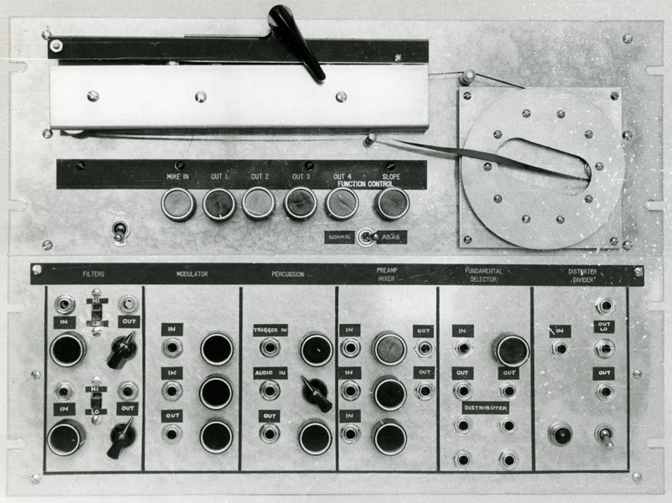
The practical application of the audio-controlled percussion device within a system for the production of new musical effects is shown in Figure 5. The sound of a bongo drum triggers the percussion circuit, which in turn converts the sustained chords played by the organ into percussive tones. The output signal is applied to a tape-loop repetition unit that has four equally spaced heads, one for record and three for playback. By connecting the record head and playback head 2 in parallel, output A is produced. By connecting playback head 1 and playback head 3 in parallel, output B is produced, and a distinctive ABAB pattern may be achieved. Outputs A and B can be connected to formant filters having different resonance frequencies.
The number of repetitions may be extended if a feedback loop is inserted between playback head 2 and the record amplifier. The output voltages of the two filters and the microphone preamplifier are applied to a mixer in which the ratio of drum sound to modified percussive organ sound may be controlled.
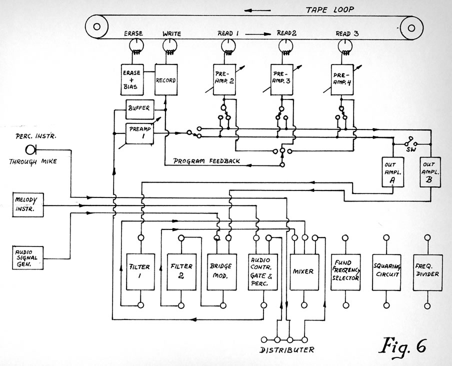
A presentation dealing more specifically with the tape-loop device and the sound-processing modules used in the synthesizer is shown in Figure 6.
The program material originating from the melody instrument is applied to one of the inputs of the audio-controlled gate and percussion unit. There it is gated by the audio from a percussion instrument. The percussive melody sounds at the output of the gate are applied to the tape-loop repetition system. Output signal A — the direct signal and the information from playback head 2 — is applied through amplifier A and filter 1 to the mixer. Output signal B — the signals from playback heads 1 and 3 — is applied through amplifier B to one input of the ring-bridge modulator. The other ring-bridge modulator input is connected to the output of an audio signal generator.
The mixed and frequency-converted signal at the output of the ring-bridge modulator is applied through filter 2 to the mixer. At the mixer output a percussive ABAB signal (stemming from a single melody note, triggered by a single drum signal) is obtained. In its A portion it has the original melody instrument pitch while its B portion is the converted nonharmonic overtone structure, both affected by the different voicings of the two filters. When the direct drum signal is applied to a third mixer input, the output will sound like a voiced drum with an intricate aftersound. The repetition of the ABAB pattern may be extended by a feedback loop between playback head two and the record amplifier.
When applying the human singing voice to the input of the fundamental frequency selector, the extracted fundamental pitch may be distorted in the squaring circuit and applied to the frequency divider (or dividers). This will derive a melody line whose pitch will be one octave lower than that of the singer. The output of the frequency divider may then be applied through a voicing filter to the program input of the audio-controlled gate and percussion unit. The control input of this circuit may be actuated by the original singing voice, after having passed through a low-pass filter of such a cutoff frequency that only vowels —typical for syllables — would trigger the circuit. At the output of the audio-controlled gate, percussive sounds with the voicing of a string bass will be obtained mixed with the original voice of the singer. The human voice output signal will now be accompanied by a coincident string bass sound which may be further processed in the tape-loop repetition unit.
The arbitrarily selected electronic modules of this synthesizer are of a limited variety and could be supplemented by other modules.
A system synthesizer may find many applications such as exploration of new types of electronic music or as a tool for composers who are searching for novel sounds and musical effects. Such a device will present a challenge to the imagination of composer-programmer.
The modern approach of synthesizing intricate electronic systems from modules with a limited number of basic functions has proven successful in the computer field. This approach has now been made in the area of sound synthesis.
With means for compiling any desired modular configuration, an audio system synthesizer could become a flexible and versatile tool for sound processing and would be suited to meet the ever-growing demand for exploration and production of new sounds.
Social top