Electroacoustic and Computational Feedback Synthesis
An interactive lecture-demonstration and study of electroacoustic and computational feedback synthesis which outlines the techniques, methods and materials required to realize an electroacoustic feedback system instrument and computer-based feedback system loop for the purposes of the synthesis of complex sounds. Diagrammes the results and systems through spectrograms and sound samples generated using the techniques described. Analyzes the sound phenomena generated through sound samples and spectrograms as phenomenon with similarities to natural forms, exhibiting fractal self-similarity, and the topological mixing of pitch, amplitude and duration; a characteristic behaviour of a chaotic (indeterminate) iterative function system. A recurring sound signature is also identified in outer space electromagnetic data sonification, isolated and re-synthesized. The natural harmonic series is generated through tuning the feedback loop by system delay unit regeneration. A non-interferential method of interacting with a chaotic feedback system for the optimal synthesis and observation of the sound phenomenon generated is presented.
This article represents sonological research activities from the inception and development of an electroacoustic feedback system instrument to the migration and integration of real-time computational feedback system methods and techniques for the production of complex sounds. It provides sound samples, spectrographic analysis, methods, materials and results, and discusses unique sound phenomenon generated by an indeterminate (chaotic) feedback system and electroacoustic computer feedback system instrument. The study seeks to convey new methods and techniques for the synthesis of sound and provide methods of interacting with a chaotic feedback synthesis system for optimal iterative phenomenon generation and observation.
Feedback phenomenon processes and systems are understood through our direct experience with the world, are observed in many natural systems, and have been successfully applied to many disciplines and technologies. Standard control theory (Åström and Murray 2008) formalizes the use of feedback for the objective of corrective action of the behaviour of a dynamic system, resulting in system stability. For the purposes of the generation of sustained states of feedback sound phenomenon, an abbreviation of the standard control theory definition of feedback guides the research and development:
Feedback is a process or phenomenon in which some portion of the output of a system is returned to its input for the synthesis of sound.
In the generative state of a feedback system, loop gain is increased and seeded with sound, coaxing the system into oscillation, but not to the extent that it causes catastrophic oscillation of the system, where system failure or damage would result.
This study is of interest and validity to the scientific and artistic communities of electroacoustic and computer music for these outcomes:
- Outlines and demonstrates the concepts, methodology, tools and techniques required to realize an electroacoustic, computational and integrated feedback system (and instrument) using a sound-producing acoustical body (a plate) within an electronic component feedback loop in a state of chaotic generative sound synthesis;
- Realizes a computer-based feedback synthesis system using unit generator audio software programs and real-time DSP input and output hardware / software;
- Identifies, isolates and re-synthesizes sound phenomenon exhibiting natural and fractal forms in all sound dimensions, finding similar natural system forms in outer space electromagnetic energy data and its visualizations;
- Demonstrates and explains the synthesis of the natural harmonic series in a feedback system by tuning the feedback loop;
- Offers methods and techniques of interaction, performance and operation with a real-time chaotic integrated feedback system and loop instrument, and the observer / performer / researcher to optimize the synthesis of emergent fractal feedback sound phenomenon and signatures intrinsic to the feedback synthesis techniques in the electroacoustic and computational realms;
- Outlines future research goals and work in the field appropriating and realizing large external plate resonators (bridge, metal sculpture) playable in concert and by the participants (one person or a group of individuals), and developing spectrogram software capable of higher resolutions for a fractal zoom deeper into the emergent waveform phenomenon and micro-soundscape worlds.
To fully isolate and create the self-generating sound signatures, a non-interferential approach is used, avoiding quantum observational effects (that the observation of one aspect of a particle introduces uncertainty in other simultaneous measurements) or unintended consequences (outcomes that are not intended by a purposeful action) in interacting with the chaotic feedback system. This approach will improve the production of fractal sound forms in an open or tuned, positive or negative feedback, closed loop electroacoustic-computational feedback synthesis system and loop.
The Standard Feedback Loop
The classic feedback loop diagram (Fig. 2) which is formalized in control theory is fundamentally concerned with the prediction, stability and control of a system using negative feedback to direct the dynamic behaviour of the system. To generate feedback sound phenomenon, we seek to decrease controls and increase the chaotic state of the system loop amplifying loop gain and input perturbation, reducing loop control and operator interference, leading the system into a generative state of chaotic generative oscillation.
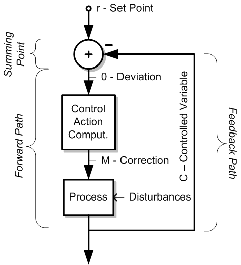
In Figure 2, the standard control theory feedback system is diagrammed, showing the system summary sections of input, summing point, forward path and feedback path. The process unit is driven by a control action computation unit, fed from the r‑set point and feedback path, through the summing point.
The Instrument Research Metaphor and Normalization of the Control Theory Feedback Loop
Research guided by the “instrument” metaphor on a systems level, and viewing sound as process, normalizes the process unit to a feedback system, the control action computation unit factors to the plate resonator body, and r‑set point as emitter (sound input signal), and loop gain of the feedback loop for the interactive feedback system synthesis of sound.
Methods and Materials
The Electroacoustic Sheet Metal Feedback Phone System Instrument
An electroacoustic feedback synthesis system instrument is shown in Figure 3, in the normalized form. The forward path of the feedback system begins after the summing point, where the line level feedback path output is routed to a power amplifier, then to the nozzle transducer using a run of speaker cable and spade connectors (bottom of plate). The amplifier to the nozzle transducer is matched in power and impedance (8 ohm, 25 watts) for maximum power transfer. This completes the basic chaotic instrument feedback system loop.

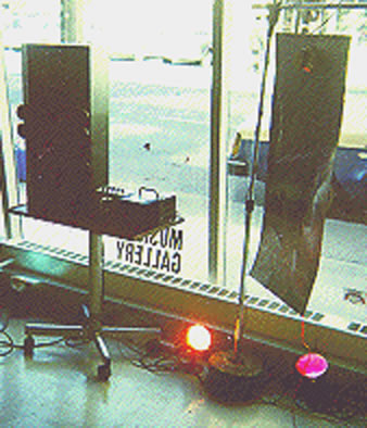
A plate (metal or similar) for the support transmission of sound and performer interaction (sheet metal plate, 0.62 x 0.91 m) is selected. Two electroacoustic transducers are fixed to the plate (two full-range four‑inch speakers, eight bolts with lock washers) acting as the plate nozzle (output), and plate collector (as input transducer). The plate (or sound transmission medium) is suspended at two points using rubber grommets in two 1/4‑inch holes, to decouple the transmission plate from its support. Wire loops are formed and suspend the sheet metal plate across the boom of a microphone stand (Fig. 1). A counterweight (sand bag) is used on the mic stand base to counterbalance the suspended plate, transducers, cables, connections and loop gain potentiometer mounted on the boom for performer loop gain control.
The plate collector transducer (Fig. 3) is connected to a variable resistor (potentiometer) using shielded cable soldered to it and spade connectors. This signal is routed down the instrument support to an external pre-amplifier, bringing the signal to line level. Next, the feedback signal amplitude is multiplied in real-time by an automatic gain control (AGC). This is a key component in the feedback system loop to enable low level sound in the process of wave propagation dissipation across the plate to be amplified and sustained, increasing system gain inversely with amplitude levels (Fig. 3 includes the I/O transfer function curve of the AGC in the unit). We arrive at the summing point, and tap the loop output here with a “Y” cable (line level), sending this line level signal to an external system speaker and amplifier. This allows for the monitoring of the instrument’s electrical outputs, and is redirected back into the feedback loop (disturbances) by aiming the speaker at the instrument’s loop transmission plate. An external full-range speaker or monitor runs from a line level “Y” tap off the feedback loop and power amplifier (or a dedicated amplifier) pointed at the plate, providing the operator-performer with control of the monitoring and amplification of the electroacoustic signal, and disturbances to the plate, as well as feeding sound energy back through the plate and into the feedback system, which provides more regeneration of the chaotic sound field and feedback phenomenon.
Operation of the Electroacoustic Sheet Metal Feedback Phone System Instrument
A method of interacting with the electroacoustic feedback system instrument and chaotic system is as follows. Begin to increase system loop gain (from 0) until disturbances to the system (internal system noise, and / or external input to the plate) coaxing the feedback loop and instrument into chaotic oscillation. Using the indeterminately generated frequency of interest from this output, increase gain of the feedback loop potentiometer until that sound is brought out of the generated soundscape and into the foreground.
The operator or performer may also interact with the metal plate by bending and contorting the plate resonator, changing the plate’s sound characteristics, introducing new system state responses and Chladni plate resonances (Chladni 1787). A non-interferential approach increases sound phenomenon generated from the indeterminate feedback instrument.
Computational Feedback System Synthesis Methods and Materials
The electroacoustic feedback system (instrument) is migrated to computer software and DSP input / output medium to implement a real-time computer-based chaotic sound feedback synthesis system.
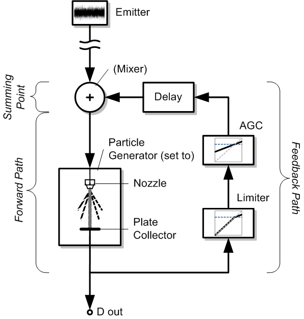
The computational feedback synthesis system diagram (Fig. 4) details the software feedback system loop and I/O of a portable real-time software (computational) feedback system. The simulation of the nozzle and plate collector of the plate and medium to support the process of sound energy wave propagation through it is achieved using a particle generator unit configured for sound reproduction and fidelity of transfer using real-time granular synthesis for plate simulation. A limiter is used in the loop to avoid catastrophic oscillation. The system must contain some delay time, and the vital AGC (automatic gain control), to allow the sustained synthesis of sounds within the electroacoustic or computer feedback loop.
System delay is a requisite and is simulated by the delay unit generator (though computation delay of the computer system may be used as a substitute if no loop tuning is required). To avoid catastrophic system oscillation, a limiter is used in the feedback loop to maintain amplitude below the critical level catastrophic oscillation state. The Vout is sent to a real-time DAC providing a tap of the feedback system loop for line level audio.
Essential Feedback Loop Amplitude Vectoring and Multiplication
The AGC unit in the feedback system loop functions in the same way in software and in hardware for the electroacoustic feedback system loop, as a loop multiplier and dynamics transfer function of increasing system gain inversely proportional to sound amplitude within the feedback loop. This essential AGC transfer function multiplier in the feedback system loop, and in the computational feedback system loop, serves to raise the level of decreasing sound energy still propagating through the plate and medium, creating sustained feedback through the plate, in the modelling of the sheet metal instrument for the synthesis of sound.
The Emitter as Sound Energy Inputs to the Feedback Loop
The sound emitter is a concept / visualization borrowed from computer graphics animation where an object provides continuous particle output for the continuous generation of sparks, smoke, water and fire; a descriptive analogy for these 1- to 3‑second, looped or continuous sounds and samples. The emitter also provides a necessary sound energy to initiate the feedback loop into oscillation and sound synthesis.
A summing point is simulated in a mixer unit generator, providing variable signal entry and output of the feedback path with the emitter feeding into the system feedback loop.
A personal computer of sufficient speed and memory to host the feedback system simulation software and I/O tasks was used for the study. Unit generator real-time software is used to realize the feedback system loop running in real-time on a laptop (2 GHz, DAC I/O) with limiter and AGC plug-ins. The simulation of physical plate wave transfer characteristics is achieved using real-time particle synthesis set to allow maximum fidelity of input sound to output in the feedback loop (Truax 1988). This is achieved using 0 (zero) pitch transposition, and large overlapping grain windows with durations of 500 ms to 450 ms.
Research Method
The research method used was to identify the anomalous sound phenomenon generated by listening and spectrogram analysis to identify, analyze, pursue, isolate, re-synthesize and visualize these emergent iterative sound phenomenon. Identifying similar output forms arising from natural systems (tree structures and branching as an instance of fractal self-similarity), formalized fractal mathematics morphologies (Campbell 2013, after Mandelbrot 1977) reveals similarities of form and behaviour. The recurring sound phenomenon generated were also found in the sonifications (audification) of outer space energies (Audio 6).
Integrated Electroacoustic and Computational Feedback Synthesis — Methods and Materials
Combining both electroacoustic and computational feedback synthesis instrument feedback loops with a real-time computer hardware / software “bridge” of the feedback loop, and a 6 x 2 audio mixer (summing point) with two pre- and post-auxiliary sends, allows for full loop routing between both the electroacoustic and computational realms, and opens up the potentially unlimited sound palette for the instrument.
Results
The Electroacoustic Sheet Metal Feedback Phone System Instrument
In preliminary testing and development of the instrument, loop gain was set to 0 (‑∞ dB), and gradually increased. This results in the failure to produce sustained transmission through the sheet metal plate medium of the electroacoustic instrument. Rather, the feedback process sidestepped the metal plate transmission path and produced microphonic feedback across the two electroacoustic transducers. An AGC was developed and inserted into the electroacoustic feedback system loop, which counteracted the error state and produced a wide range of continuous metallic feedback sounds, electronic and acoustic (Audio 1).
Cross-transducer feedback of the system fail state was a highly instructive event in the development, analysis, simulation and realization of the feedback system instrument’s origin and use in the field.
In the electroacoustic instrument, there is an overall tendency for pitch to go “up” (glissando + accelerando), similar to sounds produced from the computational feedback system loop.
Computational Feedback System Synthesis Results
Spectrogram and Sound of a First Phenomenon
The sound of the first occurrence of a unique phenomenon which emerged when progressively overdriving a software feedback loop, with a slowly changing filter frequency sweep generator and triangle wave in the feedback loop, can be heard in Phenomes 1–8 (Audio 2).
From the background sound level of the feedback loop, approximately 12 unique sound phenomenon signatures from the foundational sound emerged. These foreground sound phenomenon occurrences contain a large amount of sonic detail within them.
A single sound phenomenon (6.5 seconds) is shown in a spectrogram starting at 2:48. Figure 5 shows a “bubbling” sound underneath the filtered triangle wave drone, comprised of swooping pitch objects; self-similar sound strokes occurring in a cluster of durations, amplitude and pitch trajectories.
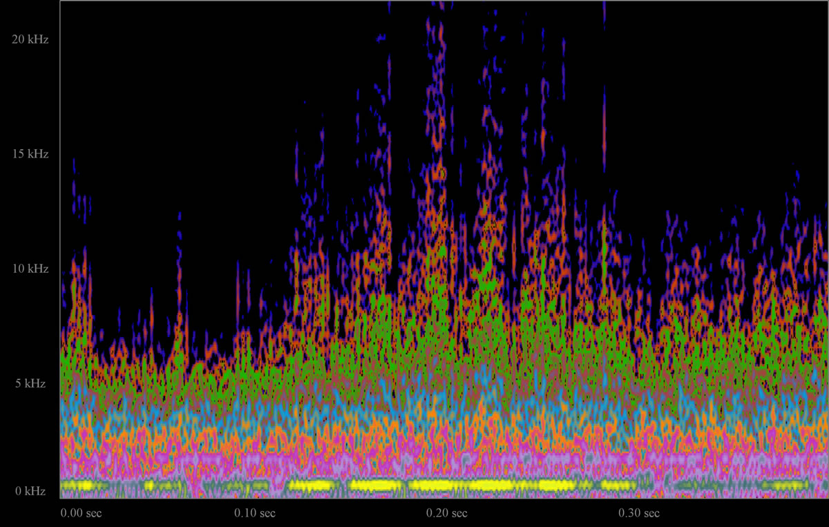
A detail spectrogram of one phenomenon is shown in Figure 6, exhibiting a forest of tree-like cone shaped objects which contain a large amount of waveform detail (scalar zoom self-similarity). Waveform topology is shown as colour intensity (amplitude) in the z‑axis, pitch (in Hz) in the y‑axis and time in the x‑axis, with colours selected to highlight amplitude variations and waveform detail. Observed are micro-waveform phenomenon showing cones (trees) with latticing, amplitude peaks in a vein-like fracturing, iterative forms, dimensionality of cone shapes with waveform filigree, nodes (silence points), node clustering and node chaining.
System-Generated Sounds Tend to go “Up” in Pitch
There appears to be a continuous propensity of all of the feedback generated sounds to go “up” in pitch during their short time (system) to time (continuous) generation of a full bandwidth sound spectrum, observed in the generation of sound by the feedback system and loop.
The “sound stroke” signatures were re-synthesized with a computational feedback synthesis system, using a sine tone as input (Audio 3).
A spectrogram (Fig. 7) shows the sound of fractal branching re-synthesis generating these types of iteratively rising pitch signatures.
Sound Topology and Spectrographic Geography of the Mesa Spectrogram
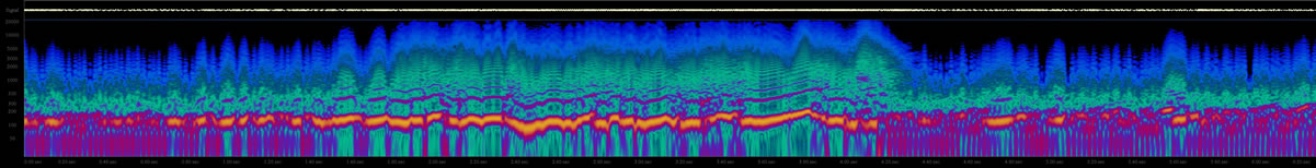
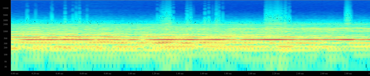
The mesa sound spectrogram (Fig. 8) was sampled from the piece Clock is Ticking and contains an image which appears to be the geographic land formation of a mesa, with a sloping variegated valley and what look like patches of earth on flora in a natural environment.
Spectrogram Scalar Zoom Self-Similarity
One recurring effect observed in this instance and in all of the sounds and spectrograms generated is the continued revealing of a microcosm of increasing detail as scale is magnified (in listening and spectrogram analysis). This effect was observed to be like the Mandelbrot set zoom, showing each part of the set to be a reduced-size copy of the whole. Self-similarity abounds in the clustering and chaining of node point silences, tree and cone structures, and sound phenomenon.
Loop Tuning Results — The Natural Harmonic Series Synthesized
It was observed that an increase of feedback to the loop delay unit feedback regeneration will result in the ordered pitch ladder of tones in the natural harmonic series (f, 2f, 3f, …), transforming the untuned indeterminate feedback system state to a tuned one.
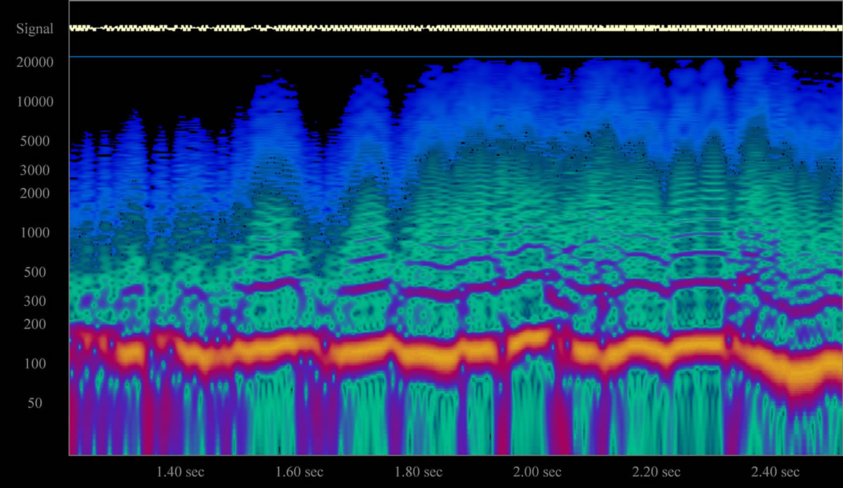
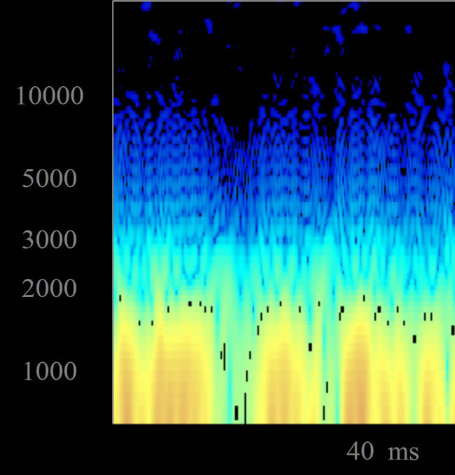
A spectrogram of a three-second sample from Kennedy’s Journey is shown in Figure 9. As the trace of the sound generated is magnified, distinct cone-shaped edifices of low amplitude harmonic forms rise like towers of high frequencies. Magnification shows the fundamental frequency peaks (dark orange), and fields of nodes (darker “silence points”) forming an arc below the cone shaped harmonic structures when they occur.
A 400-millisecond spectrogram view of Kennedy’s Journey follows, showing sound parameter blending, inter-relating with high frequency peak events and displaying a visual topology reminiscent of fire or a viscous liquid beading on a surface (Fig. 10).
A spectrogram detail of the generated harmonic series (Fig. 11) shows low amplitude high frequency feather-like plumes (-100 to 80 dBm) with dimensionality, and the existence of sound “islands” in the 10–20 kHz range.
Pitch Walkabouts and Seeding the Loop in “Identify”
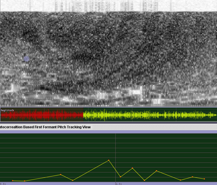
A sample of a woman’s voice saying the word “identify” was used as an emitter to seed the feedback system loop periodically with only loop gain increased and decreased over the duration of the piece and recorded for analysis (Audio 5). A non-interferential approach was used in an effort to avoid quantum observational effects at any inhibition to the generation of sound phenomenon by the feedback system.
It may be observed by audition how the voice sample as emitter introduced impacts the feedback system loop in an excerpt from my 2011 piece, Identify (Audio 5). The emitter was repeatedly fed into the loop in at 20-second intervals, and greatly modifies the continuous sound state output at every occurrence, changing the previous system state and process in an indeterminate way.
Discussion
Electroacoustic Feedback Synthesis System Instrument
An electroacoustic feedback instrument system was developed which allows the operator-performer to produce an unlimited amount of electroacoustic feedback sounds for a performance of John Cage’s 1970 piece, Perform Feedback Twice. The electroacoustic system (instrument) behaves in a chaotic way, producing sounds that range on a continuum from harmonic oscillations to dissonant noise.
A musical instrument is deemed such by its purpose. Feedback sounds output from the instrument are viewed on a systems level, ranging from a system in a state of order to a system in a state of chaos. Individual perception of consonance or dissonance can be resolved algorithmically (Foster 1995).
System Fail State Takes the Path of Least Resistance
In beta tests, the system failed to produce sound transmission through the sheet metal plate, and instead increased loop gain produced microphonic feedback between the two transducers, “sidestepping” the intended sound path. Sound would reverberate in the metal plate, but not be regenerated and supportively summed into a state of system oscillation. Sound is viewed as the physical process of wave propagation through a support medium obeying a natural law of energy taking the easiest path, feeding back through the instrument transducers, and not through the plate medium. The path of least resistance is always taken by objects moving through a system, evidenced in natural systems, described in physics (Maupertuis 1744), and often used to describe why an object or entity takes a given path. To enable the sound energy to be sustained across the feedback system plate medium, an automatic gain control (AGC) was developed and inserted into the feedback system loop. This amplitude vector multiplication in the loop is required for continuous electroacoustic and also computational feedback system operation for the synthesis of feedback phenomenon and sounds.
The AGC’s transfer function on waveform energy amplitudes is shown graphically in the AGC box unit section of the systems diagrams (Figs. 3 and 4). Within this, an I/O transfer function square, the corner to corner diagonal showing a 1:1 input to output transfer. The darker line shows the transfer function of the AGC, where lower levels of sound are amplified more. The AGC is applied to all sound levels with no threshold of operation. This is shown in the diagram by the I/O transfer line, with unity at maximum level. The AGC works to turn up the decaying travelling wave energies in the plate, thereby supporting their continuous regeneration within the feedback system loop.
Recurring sound phenomenon signatures, identified, isolated and resynthesized in the computational feedback systems operation, are also found in the electroacoustic system instruments output.
Research Driven by the Instrument System Metaphor
A systems instrument approach to the realization of a physical interactive electroacoustic instrument was imposed by the requirements of the activities to create an instrument to produce feedback. This systems view was advantageous in formalizing techniques and methods arising from the research and aided their migration to computer software and hardware. The sonological research defines a path of Kaizen [continuous improvement], from the conception of the electroacoustic instrument, to the computational implementation and integration with the instrument.
Computational Feedback Synthesis Systems Discussion
The first emergent computational sound phenomenon (Audio 2) occurred in a dramatic loud-soft form. This binary amplitude dynamic is an analogue to the graphical representation of the Mandelbrot set, which plots numbers in the set in black. The perception of the phenomenon was fundamentally observed in the system output by arising from the background to foreground perception (Tenney 1978). Waveforms heard and observed in the spectrograms have tremendous scaling detail, which is the primary example of fractal scalar-self similarity (for example, in coastline length measurements).
The clue that the system was responding like a natural system and producing fractal forms was underscored by the iterative nature of the system, and demonstrated in the following iterative fractal equation (Mandelbrot 1977, 116):
Equation 1: zn+1 = zn2 + c
The feedback phenomenon morphologies can be partly explained as examples of scalar self-similarity in sound forms, whose effects can be studied in nature and described by fractal geometry. I found a similar sound phenomenon in space energy data visualization from Voyager 1, a type of natural sound named “Chorus”.
Isolating a Sound Element of “Chorus”: The “Sound Stroke”
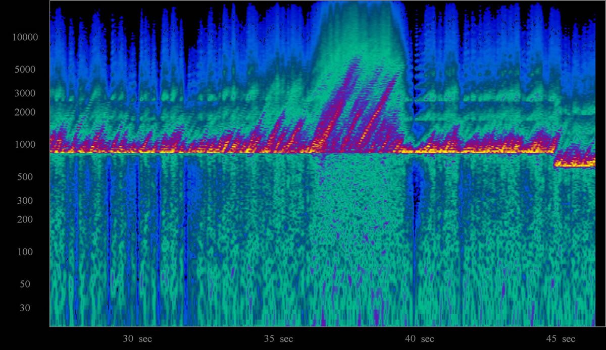
In seeking to identify the recurring fractal signature form found in many sounds generated by the feedback system loop, one element of Chorus is isolated and shown in the next spectrogram (Fig. 12).
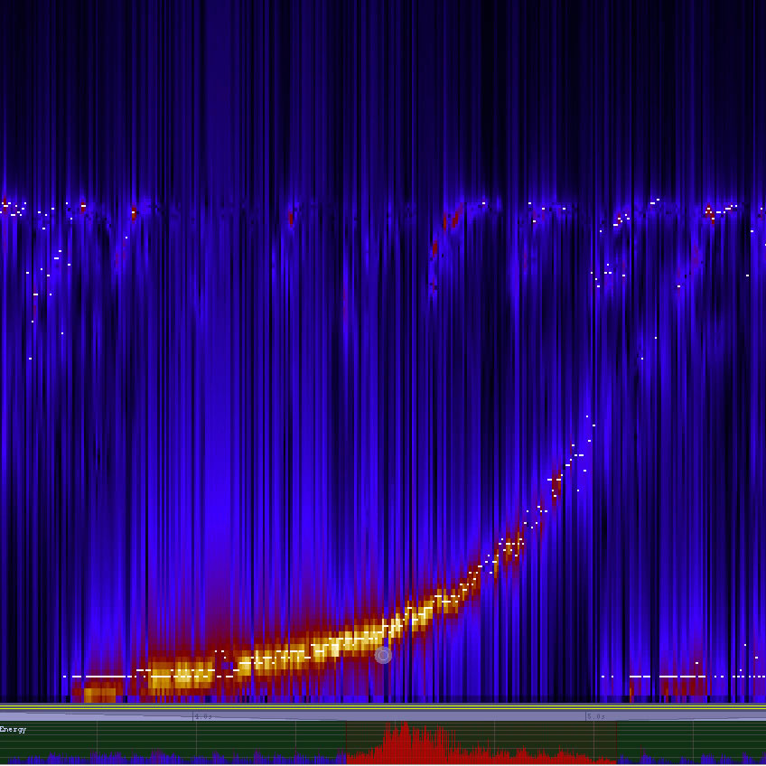
The sound figure is observed to exhibit self-similarity in its logarithmic pitch rise, an amplitude blob and a tail which has a streamlined teardrop shape. Pitch rises in a fractal manner (glissando-accelerando), at each second in time re-doubling its pitch rise trajectory. A timbral transition from the focused point fragments into an increasingly broad spectrum towards noise the end of the sound signature tail. The 11 “L”‑shaped repetitive sound figures in the Mesa Spectrogram (Fig. 8, above) are the one-second tick emitter sounds, feeding the computational synthesis loop. These increasingly rising pitch signatures are also found in outer space electro-magnetic data visualizations, as can be heard in Audio 6.
The outer space “Chorus” signature is an expression of banded self-similar sound signatures found in many generated outputs. The sound stroke is an expression of sound attributes exhibiting scalar self-similarity over time in all sound attribute dimensions: amplitude scalar process over time shows an iterative onset, growth and decay, while pitch shows a similar transition from a small Q bandwidth focus to multiple noise frequencies in the tail.
These sounds rise in pitch exponentially due to the sound energy sustained within the loop taking the easiest path. It takes more energy to sustain low frequency signals within the feedback loop over time than it does to sustain high frequency sounds, an effect shared by electromagnetic space energy and mechanical sound energy.
The tree, vein, islands, clusters, feathering and forms synthesized share a characteristic of natural system outputs due to their iterative nature of self-similarity, and their shared description in the fractal geometry of nature (Mandelbrot 1977).
Pitch Walkabouts Exhibit the Topological Mixing of Sound Attributes
The pitch walkabouts in the “identify” sample showed clues that the sound was behaving on a meta systems level, where aspects of sound (pitch, amplitude, frequency, duration) were interrelating and affecting each other on a system level (Audio 5). The effect of topological mixing means that the system will evolve over time, so that any given region or open set of its phase space will eventually overlap with any other given region.
The feedback systems can be described as an iterated function system (Falconer 1990) loop containing complex amplitude transform multipliers; a chaotic system which can produce fractal sound forms.
An iterative function system is used in mathematics to produce fractals, and describes the feedback system and loop with its complex amplitude compression and vectoring multiplication in the loop (limiter, AGC), a portion of the output directed back into the input, producing continuous sounds exhibiting the topological mixing of pitch, amplitude and duration, in auditory, perceptual and spectrogram analysis. In the pure computational state of the feedback system loop, any interference or measurement or change introduced by the operator-performer will order the system and predispose it to produce sound phenomenon which is self-similar to the emitter or input gestures into the instrument feedback loop.
Characteristics of a Chaotic Feedback System Instrument
In my experience playing and continuously developing the electroacoustic-computer music feedback system and instrument, it displays these characteristics of a chaotic (indeterminate) system, as described by Larry Bradley (2008):
- Extreme sensitivity to initial conditions (enabling the instruments to be played using the Butterfly Effect);
- Cause and effect are not proportional (instrument will suddenly stop producing sound);
- Nonlinearity (input does not always equal output).
Additionally, the following characteristics are encountered:
- Exhibits topological blending of sound parameters (pitch, amplitude, duration, timbre) in the pure computational form;
- The optimum operational, observational and synthesis results are produced using a non-interferential approach to the indeterminate loop avoiding quantum observational effects, and unintended consequences, any interruption or inputs to the loop impose an ordering and stability to the system;
- The feedback system loop will transition from an untuned loop state to a tuned loop state by adding local delay loop regeneration in order to produce only pitches from the natural harmonic series that are arithmetically related to the fundamental {ƒ, 1ƒ, 2ƒ, …}.
Peaks and Node Clustering Phenomenon, or: “Why are there holes in my Spectrogram?”
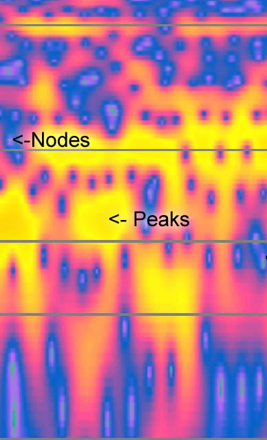
Peaks and nodes can be used to describe the spectrogram waveform topology. Nodes appear in Figure 13 as circular holes showing a drop in loudness across the topology of the waveform amplitude. This effect can be partly explained as the topological mixing of amplitude, pitch and duration within a generative system supporting recursive sound energy. Why there is node clustering and chaining in the sounds and spectrograms, and whether or not these nodes silences go down to amplitude zero, remains to be explained with more detailed spectrogram waveform analysis.
Other phenomenon exhibited by the feedback system loop, such as vein shapes, tree and cone shapes, fracture, islands, can be viewed as phenomenon of an iterated function system, the product of which is fractal and shares the forms of natural systems.
Optimizing Interactions with a Chaotic System for the Synthesis of Sound Phenomenon
To fully isolate and create the self-generating sound signatures, a non-interferential approach of avoiding quantum observational effects or unintended consequences was used. This approach has been proven to optimize feedback synthesis and control by using the lowest real part of energy Eigenvalues (Itami 2010).
In a purely indeterminate system, any interactions with it will impose an order to it, such as an emitter input or control gesture. In experiments with seeding the loop with low amplitude emitter signals into the computational feedback loop (-80 dBm), the feedback-system-generated sound phenomenon were iteratively similar to the source input sound (Foster 2011).
Tuning The Computational Feedback System Loop
We see that the chaotic synthesized output of a computational feedback system loop can be ordered by applying regenerative feedback to the delay unit, producing frequency peaks all within the natural harmonic series. The fundamental frequency of this series is directly related to the delay time of delay unit and regeneration amount of the local feedback loop within the larger feedback loop within the feedback system. The regeneration of signal set by delay unit time and local feedback amount and imposes a natural harmonic order to the synthesized frequency spectrum.
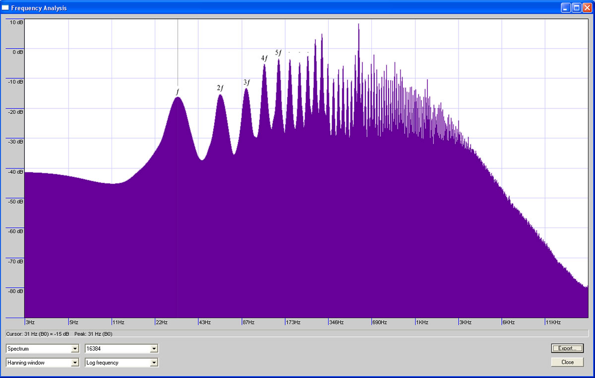
A frequency spectrum graph of a 10‑second sample from the generated sound spectrum (Fig. 14) shows the presence of a fundamental frequency peak (31 Hz rounded), and continuing up in frequency showing peaks at frequencies related to the natural harmonic series.
The fundamental frequency exhibited is related to the delay time (32 ms). Observed fundamental frequency (f) from the delay duration time is 31.25 Hz (see Eq. 1, above). The second harmonic frequency peak, the octave or F1 (2f) was measured at 62.5 Hz.
The amplitude envelope across the frequency spectrum of the frequency response graph also exhibits a natural curve, mimicking the contour of one side of the edge of a leaf.
Consider a string (a vibrating medium with boundaries) stretched and fixed at both ends (nodes). Energy put into the system will cause the system to vibrate (peaks) and produce a fundamental frequency with a series of harmonic frequencies spatially and mathematically related to the fundamental. This could be explained by the energy introduced into the system (vibrational) finding the path of least resistance to a sustained state within the spatial boundaries of the string (length): the fundamental frequency, the next most easily sustainable frequency a centre node and with two peaks (2f, or the octave). The next easiest vibrational state path which can be sustained by the system is subject to be a spatial multiple of the total string length.
How does this view of the physical harmonic series from the string system explain the ordering of the feedback loop to produce this natural series in the computational medium? In a tuned loop, when a sound enters the feedback loop it will be soon impacted with a copy of itself after the set delay time, and repeatedly depending on the time duration and regeneration setting of the system loop delay unit. This impact of duplicate sounds introduced into the feedback loop is stated as time to impact and may be converted to frequency using the following equation, where duration is in seconds (ms / 1000) and frequency in Hz:
Equation 2: Frequency = 1/duration
Time to impact of input sound copies produces a repeated imposition on the feedback loop, generating a fundamental frequency (a pitch) and imprinting the input repetitively at the delay time, predisposing the loop to more easily support sounds of frequencies arithmetically related to the fundamental. Sounds repeatedly impacting the feedback loop produce a fundamental frequency (delay time to impact), and upwards through the harmonic tier in paths of vibrational states of least resistance and multiples of the fundamental.
Why Vibrating Strings and Tuned Loop Feedback Systems will Generate the Harmonic Series
Given the physical system fail state of cross transducer feedback which occurred in development, the mechanical feedback sound phenomenon took the path of least resistance, a characteristic of the behaviour of natural (fractal) systems and mechanical energy flowing to the easiest paths.
Consider a string (as system) stretched between two fixed points in space, with freedom of movement on the z plane, limited by physical space, under tension with the mass and springiness required to support string waveform energies. Energy is put into the string system, causing it to vibrate at its fundamental frequency. Input energy flows into an array of natural harmonics, 2f (or octave) being the next physically determined harmonic of the fundamental, the easiest path state of the vibrating string system. More harmonics spring from the fundamental as states of least resistance by multiples of physical length in space and next least resistance to energy in a ladder of related multiples. What results is “tiers of paths of least resistance” existing in the string system to support waveform energies put into the vibrating system, creating a natural harmonic series physically and mathematically related to the fundamental frequency by the physical limitations of matter and the vibrating body in space.
In the computational feedback systems’ synthesis of sound in a tuned loop, the once chaotic pure iterative function system’s feedback system loop is tuned by a delay unit with local regeneration on. Any sound (emitter) input to the feedback loop with a local regeneration delay time of less than 50 ms will predispose or tune the loop to frequencies by virtue of its repeated time to impact, reinforcing the presence of the sound in the feedback loop. The repeated impact of sound copies entering the feedback loop through delay unit time regeneration effectively tunes the feedback loop.
Biomechanical Ease of Coupling Auditory and Visual
The sound signatures generated mimic natural sounds and have an ease of coupling to the human hearing system and its biomechanical interface. The visual preference and perceptual ease of natural fractal forms is also validated by research showing that humans display a consistent preference across fractal images whether “generated by nature’s process, by mathematics, or by the human hand” (Spehar et al. 2003).
It has been shown that the auditory perception of water does not change with its scale. Many natural signals and environmental sounds exhibit scale-invariant statistics: their structure is repeated at multiple scales (fractal). These forms have been shown to have a neural correlate as neurons in the ascending auditory system respond preferentially to sounds showing scale-invariant features across the frequency spectrum (Geffen et al. 2011). Knill (1990) interpreted this finding in terms of the efficiency of perception, with our perceptual systems being maximally tuned for structures that are likely to occur in the environment (Schmuckler et al. 1993, 656).
Feedback itself is an iterative phenomenon and its use in the synthesis of sound does predispose the outputs to sound phenomenon displaying fractal scalar self-similarity and ease of biomechanical coupling.
Future Research
Future research driven by the sonological research directive includes:
- Developing more powerful spectrogram analysis software which may, through magnification, reveal levels of increasing waveform detail and node depth;
- Building up from a large resonant metal structure in the field (sculpture, bridge) the resonant plate elements for the realization of a feedback synthesis system interactive instrument for one or many operators 2[2. For one possible realization, see the documentation of the installation-performance KATA-STROPH — Nuit Blanche 2011, “A Group Futurist Art of Noise Interactive Manifesto Sound for large Industrial Orchestra” performed by Campbell Foster et al. in Toronto’s Distillery District on 1 October 2011.];
- Validating the implementation of a feedback system instrument loop using the recording studios’ mixer, limiter and AGC;
- Group learning transfer of the acquired knowledge through classes and instruction;
- Support of the Sonological Research through works, performances, artifacts, donation, support and interactive lectures.
Bibliography
Åström, Karl Johan and Richard M Murray. Feedback Systems: An Introduction for Scientists and Engineers. Princeton University Press, 2008.
Bradley, Larry. “Chaos and Fractals: What is Chaos?” 2008. Available online at http://www.stsci.edu/~lbradley/seminar/chaos.html [Last accessed 2011]
Cage, John. Song Books (Solos for Voice 3–92). Edition Peters 6806A (Solos 3–58), Henmar Press (1970), Piece #42.
Chladni, Ernst Florens Friedrich. Entdeckungen über die Theorie des Klanges [Discoveries in the Theory of Sound]. Leipzig, Germany: Weidmanns, Erben und Reich, 1787.
Falconer, Kenneth. Fractal Geometry: Mathematical foundations and applications. John Wiley and Sons, 1990.
Foster, Campbell. “A Consonance Dissonance Algorithm for Intervals.” ICMC 1995. Proceedings of the International Computer Music Conference (Banff AB, Canada: Banff Centre for the Arts, 1995).
_____. Revelations Gliese 581 — Clock Is Ticking. [Video, dur. 4:27]. 2008. Available online at http://www.youtube.com/watch?v=KTsmFRDYcik [Last accessed 20 February 2013]
_____. PLANET TRINITY — MARS Planet (2/3). [Video, dur. 8:13]. 2010. Available online on the author’s research blog http://campbellfoster.ca/2010/11/14/planet-trinity-mars-planet-section-2-of-3 [Last accessed 20 February 2013].
Geffen, Maria N., Judit Gervain, Janet F. Werker and Marcelo O. Magnasco, “Auditory Perception of Self-Similarity in Water Sounds.” Frontiers in Integrative Neuroscience. Published online 11 May 2011.
Itami, Teturo, “Optimal Feedback Synthesis Based on an Energy Eigenvalue Calculation Using Random-Walk Quantum Monte-Carlo Method.” NOLCOS 2010. 8th IFAC Symposium on Nonlinear Control Systems (Bologna, Italy: University of Bologna, 1–3 September 2010).
Knill, David C., David Field and Daniel Kerstent. “Human Discrimination of Fractal Images.” Journal of the Optical Society of America 7/6 (June 1990), pp. 1113–1123.
Mandelbrot, Benoit B. The Fractal Geometry of Nature. W.H. Freeman & Co. Ltd., 1977.
Schmuckler, Mark A. and David L. Gilden. “Auditory Perception of Fractal Contours.” Journal of Experimental Psychology: Human Perception and Performance 19/3 (1993), pp. 641–660.
Spehar, Branka, Colin W.G. Clifford, Ben R. Newell and Richard P. Taylor. “Chaos and graphics, Universal æsthetic of fractals.” Computers & Graphics 27/5 (October 2003), pp. 813–820.
Tenney, James. Heirarchical Temporal Gestalt Perception in Music: A “Metric Space” Model. York University (1978).
Truax, Barry. “Real-Time Granular Synthesis with a Digital Signal Processor,” Computer Music Journal 12/2 (Summer 1988), pp. 14–26.
Social top