It’s Not an Instrument, It’s an Ensemble
A Parallel approach to modular synthesizer design
Held in Manchester from 24–26 October 2014, the first Sines & Squares Festival of Analogue Electronics and Modular Synthesis was an initiative of Richard Scott, Guest Editor for this issue of eContact! Some of the authors in this issue presented their work in the many concerts, conferences and master classes that comprised the festival, and articles based on those presentations are featured here. After an extremely enjoyable and successful first edition, the second edition is in planning for 18–20 November 2016. Sines & Squares 2014 was realised in collaboration with Ricardo Climent, Sam Weaver, students at NOVARS Research Centre at Manchester University and Islington Mill Studios.
Background

This paper represents an attempt to document a two-year deep immersion into the world of new modular synthesizers and the evolution of a rather specific type of instrument: an 8-channel, 8-voice multi-timbral synthesizer built around a hybrid digital/analogue model and a unique tuning system.
To an extent, this journey has represented a coming home of sorts. Although my career in electronic music, centering around my time with Jonty Harrison and BEAST in Birmingham (UK), has largely been built around a musique concrète approach based on the manipulation of acoustic sound, synthesizers have never been far away. In fact, that’s where I began: my interest in electronic music was initially sparked (around age nine or ten, I think) by a friend of my parents who was building a synthesizer from a kit (which I don’t recall ever being completed) and had a collection of Tangerine Dream, Kluster, Neu! and Harmonia records. Later on, at Nottingham University, I discovered an EMS Synthi AKS gathering dust at the back of the studio and this rapidly became my favourite thing. As part of my PhD, I spent six months at EMS (coincidental name, of course) in Stockholm, where I enjoyed playing in their then-underused analogue studio that had large vintage Buchla and Serge modular systems, amongst other treasures.
Later still, my first job was at Dartington College of Arts, where there were two barely-functional VCS3s and a wonderful Moog modular. Here I made my deepest foray into analogue modular synthesis, which also happened to be my first encounter with video. This was a work entitled Zoetrope, which was an attempt to unpick the illusions created by technology. To achieve this I wanted to work with the raw material of the technology itself — not bits and bytes but volts and amps. The Moog and EMS synths provided me with my audio material, alongside a set of simple techniques derived from feedback loops. In the absence of any more sophisticated techniques or technologies being available to me, feedback was also at the centre of the video material that made up the work. This formed the basis of a raw, lo-fi æsthetic that I have continued to explore in my audiovisual work to this day.
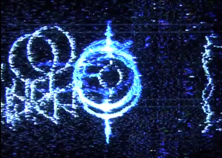
Alongside “in-the-box” computer/software-based work, I have from time to time used such low-tech analogue technology, particularly within a feedback paradigm: My 2009 piece End Transmission (Fig. 1) was built around an audiovisual feedback loop incorporating an unusual kind of “composite cramming” to produce distorted audio from video signals. I have also explored combinations of analogue and digital technology: the audio for my 2010 work Vanishing Point was produced by passing sound from old valve radios through a large bank of (digital) comb filters tuned to a variety of complex harmonic ratios. However, the analogue technology used in these pieces is very simple, and falls some way short of any recognised form of synthesis.
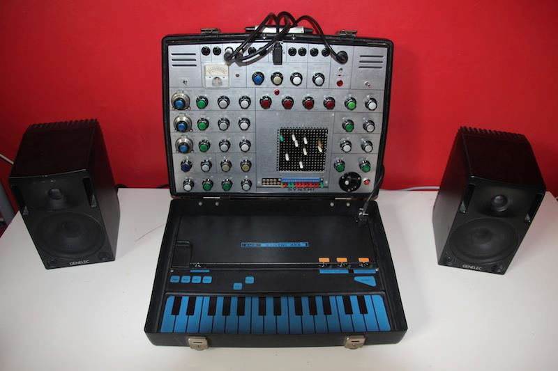
My return to the world of analogue synthesis proper was prompted by a generous offer: Odilon Marcenaro, who I knew through the Creative Music Technology courses at the Royal Welsh College of Music and Drama, offered to loan me his Synthi AKS for several months over 2013 and 2014 (Fig. 2). I was delighted to return to this wonderful instrument and had endless fun with it. I also used it for a performance at the Cube in Bristol, and found its limitations and immediacy provided a feeling of genuine performance that I’d been missing for decades. I was officially bitten by the bug.
It’s Not an Instrument, It’s an Ensemble: Design Philosophy
When the Synthi had to be returned, I decided to build my own modular synthesizer in the popular Eurorack format. As I suspect is standard practice, I spent six months plotting and planning (and saving), getting to know the landscape of contemporary modular synthesis. I watched I Dream of Wires, lurked around the Muffwiggler forum and made endless pipe-dream systems on ModularGrid. Gradually a plan for my system started to come together.
There were certain things I decided quite early on:
- I would not be using the modular synthesizer to replace my laptop, or indeed be abandoning 20 years of experience with digital technology. Rather I would use this experience in conjunction with the modular to produce a digital/analogue hybrid. However, I would not — at least initially — be incorporating any digital synthesis modules. Rather, any DSP incorporated into the system would be built myself using Max/MSP. These might include audio generators and processors, but would primarily centre around control voltage generation. Currently all CVs in the system are generated digitally using Max, whereas the audio signal paths are entirely analogue. This model suits the music I’m working on at the moment, but I’m open to bringing DSP into the audio signal chain in the future. I may also end up bringing in digital modules in the future — the decision not to do so at this stage was largely economic.
- Coupled to the above, the synthesizer would be built to entirely avoid standard equal-tempered chromaticism. In my previous forays into analogue synthesis with the EMS VCS3 / Synthi AKS and Moog, Buchla and Serge modulars, I had never used a keyboard as input. Then, I pretty much disregarded pitch entirely. Now, I am interested to explore precise pitches, but not those derived from standard Western tunings. I was particularly interested to explore intervals derived from the harmonic series, and in particular from a process of “harmonic stacking”, discussed in depth below.
- The system would be built from the ground up to be 8-channel. A spatial dimension has often been key to my work since my BEAST days. I’m interested in the idea of analogue synthesized sound as an immersive experience, and it seemed to me that this was something that could merit further investigation. Whilst a spatial dimension was integral to early electronic music by composers such as Alvin Lucier and David Tudor, it doesn’t seem to be a particularly strong current in contemporary modular synthesis practice.
- The system would be (8-voice) multiphonic. In keeping with the idea of building an immersive sonic experience, rich harmonic and timbral complexity was important to me. However, I knew that an attempt to build a truly polyphonic modular synthesizer, certainly one with eight voices, would be prohibitive in terms of cost, effort and space required. The reason I don’t see it as truly polyphonic — although this could be debated — is because it has no system for managing polyphony (although this would actually be quite easy to implement at least in part using Silent Way or Max-based software), and the voices are not uniform.
Hardware
I chose the Eurorack format largely for economic reasons, but I was also excited by the variety of modules available for the format, and the variety of manufacturers producing them. This seems to me to be the one of the most exciting things about the new modular scene, allowing genuine creativity on the part of the user in putting together a system.
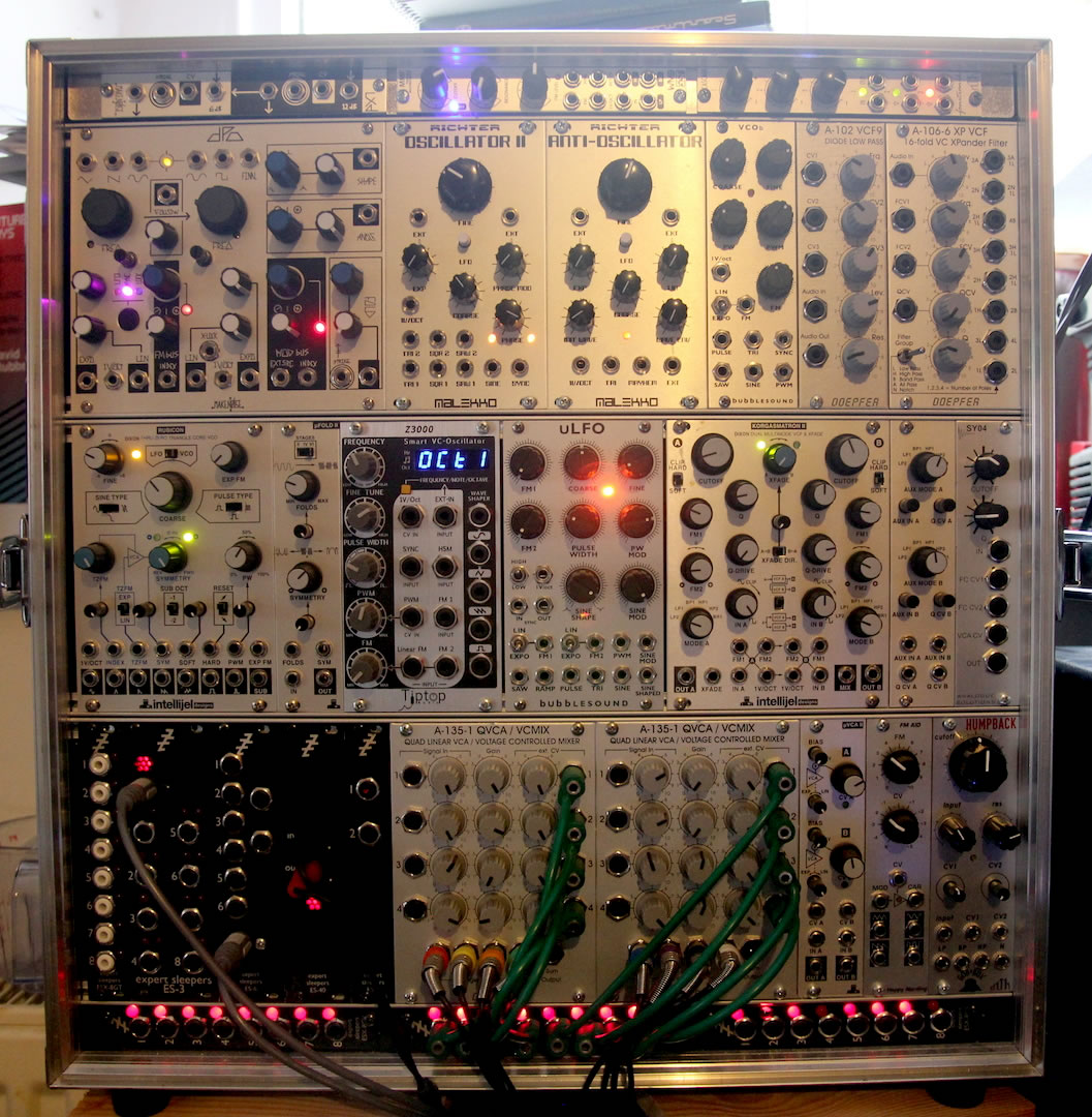
Many of the experienced people I count as influences in the field have gone to considerable lengths to build and refine a coherent instrument. Often they seem to progress from the disparate nature of a multi-manufacturer Eurorack system to something more bespoke from a single builder. I can see the benefits of such an approach, and observe that ModularGrid and the Muffwiggler forum are full of huge Frankenstein systems with little rhyme or reason to the selection of modules (other than I suspect what happened to be “hot” when they were bought). I realised quite early on that I was aiming for something between the two approaches. I think a big part of my decision-making process has been tied up in what makes modular different to working in something like Max. If one makes eight oscillators in Max (eight [cycle~] objects for example), they will all be exactly the same. In my Eurorack system I have often gone out of my way to make things as diverse as possible, but within reasonable limits: the oscillators are all analogue and mostly of fairly standard design (a possible exception being the Make Noise Dual Prismatic Oscillator, but I’m currently using this dual or “complex” oscillator primarily as two independent tone generators), but with plenty of modulation possibilities. They are also arranged in complementary pairs (DPO as one pair, Malekko/Richter Oscillator II and Anti-Oscillator, bubblesound uLFO and VCOb, TipTop Audio Z3000 mk. 2 and Intellijel Rubicon) — these are designed to make good “buddies” for FM, which will form a major part of my work as I evolve it. However, where it might have been sensible to go for 8 identical oscillators, or four identical pairs, I wanted each to have its own quirks and personality.
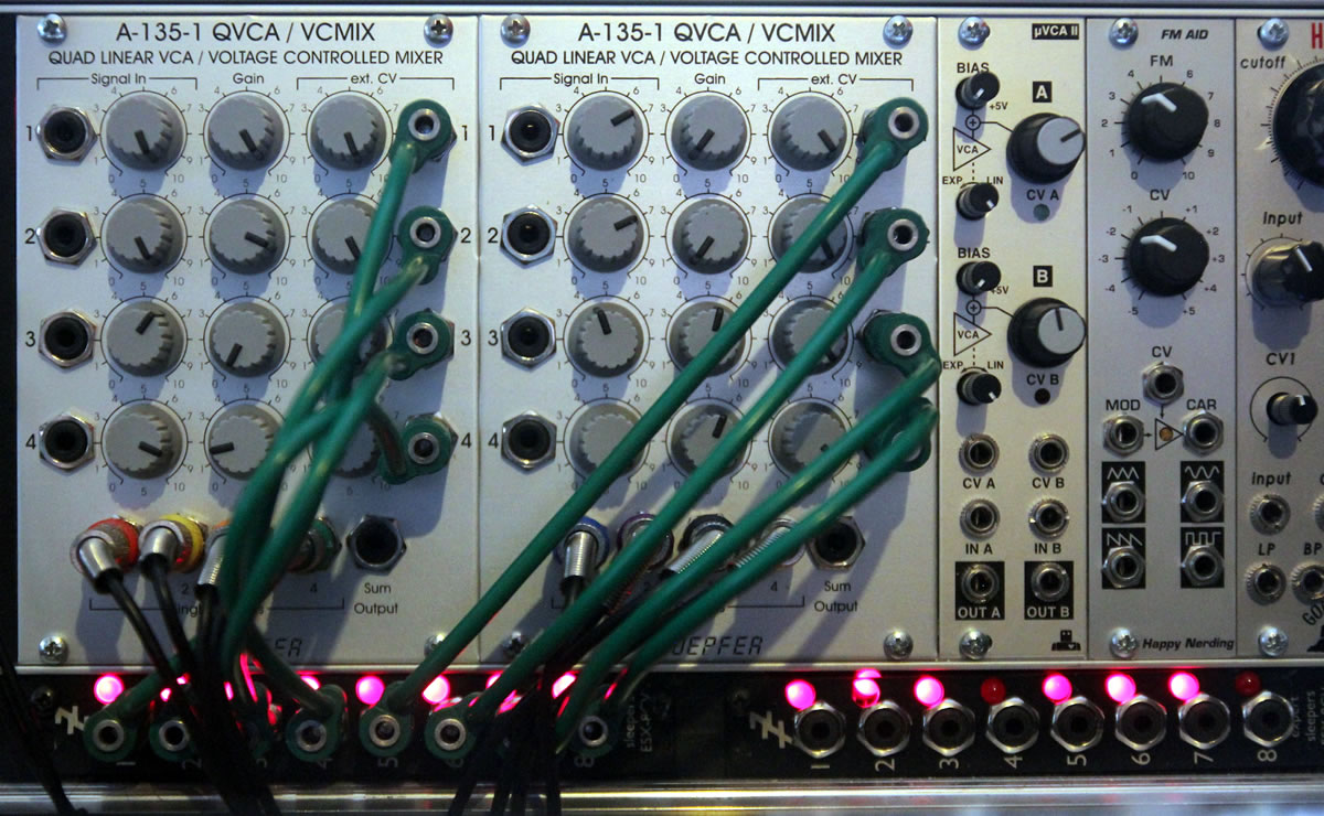
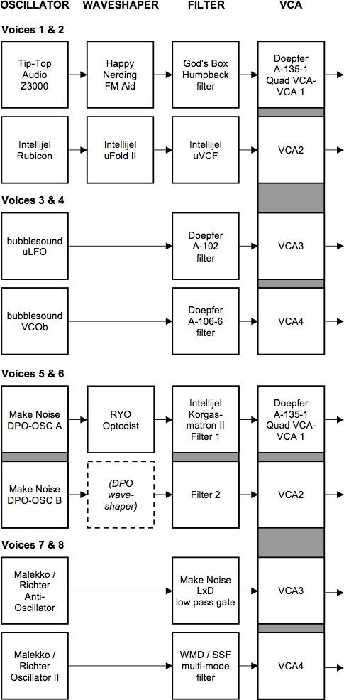
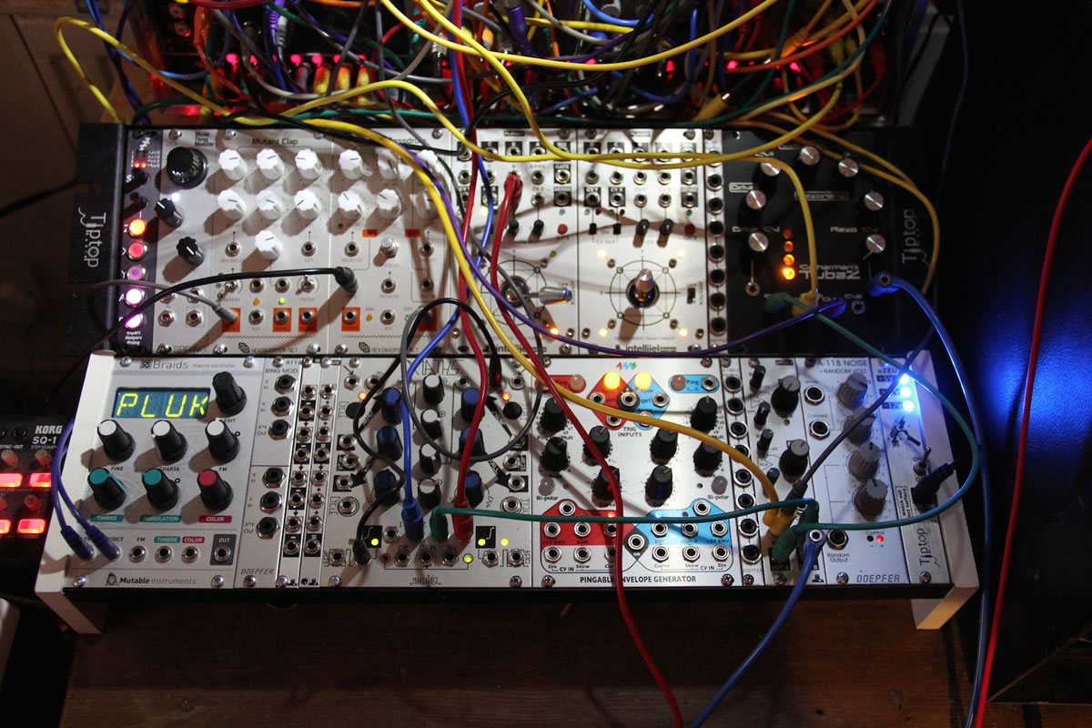
As I’ve progressed the system, I’ve realized that I’ve not been aiming at an instrument at all, but rather an ensemble. Rather than a single instrument, I see it as eight, each consisting of an oscillator and a filter (I won’t go into details here, but the filters are also all different — though often paired). Four of them have some sort of waveshaper or distortion between the oscillator and the filter, and two are passed through an Intellijel Korgasmatrion II, which has its own overdrive/clip circuit built in, in series with the filter. The eight voices are fed through a pair of Doepfer A-135-1 Quad VCA/VCMix modules (Fig. 3). These provide a VCA for each of the voices (controlled by my software via the Expert Sleepers hardware — this is detailed below) and route the audio out to the eight speakers (one voice to each speaker). In this configuration I don’t actually use the mixer capabilities of the A-135-1 modules, but they can also be used essentially as an 8-to-2-channel mixer where a stereo mixdown of the eight voices is required (Figs. 4–5).
In a Silent Way
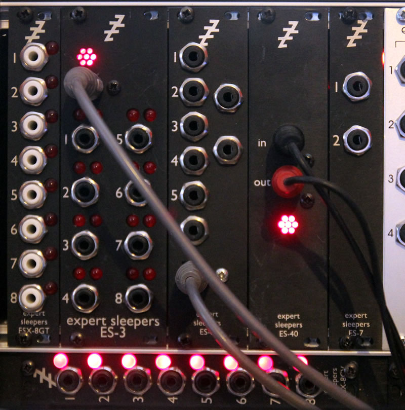
With my aim of building a hybrid analogue/digital synthesizer with eight voices in mind, I required a fairly large number of channels for audio and/or control voltages between the synthesizer and my software. At a fairly early stage, I adopted Expert Sleepers’ Silent Way software and hardware (Fig. 6), in combination with an RME FirefaceUC audio interface. This combination allows me to stretch the 18 ins/outs of the Fireface a long way: it provides me with eight audio channels to provide the octophonic playback, an additional eight channels (ADAT/lightpipe, using the Expert Sleepers ES3 module) of audio/CV running from the software to the synthesizer, 18 channels (including eight ADAT/lightpipe, using Expert Sleepers ES6 and ES7 modules, and two SPDIF, using Expert Sleepers ES40 and ES7 modules) of audio/CV running from the synthesizer to the software, and an additional 24 channels of CV and 8 channels of clocks/triggers running from the software to the synth. These 32 additional channels are provided by a clever trick of the ES40: all 24 channels are derived from an SPDIF stereo connection using a series of “header” modules connected to the ES40 — in this case three ESX-8CV modules and one ESX-8GT module. The large number of outputs (in fact, eight more are possible if required) is made possible by multiplexing the stereo signal to produce multiple outputs at lower sample rates — these are ample for CV and clock duties.
The eight channels of clocks/triggers are currently not used, though I have plans for them in the next iteration of my system. The 24 channels of CV are divided into three per synth voice. Two are used for envelopes: one for amplitude (connected to the respective A-135-1 VCA) and the other for timbre (connected to waveshaper and/or filter). The third is used for LFOs, used in a variety of ways. I initially used this one to control the pitch of the oscillators, but I found the low-bandwidth outputs provided by the module to be insufficient for the tuning tolerances I wanted to achieve (see below).
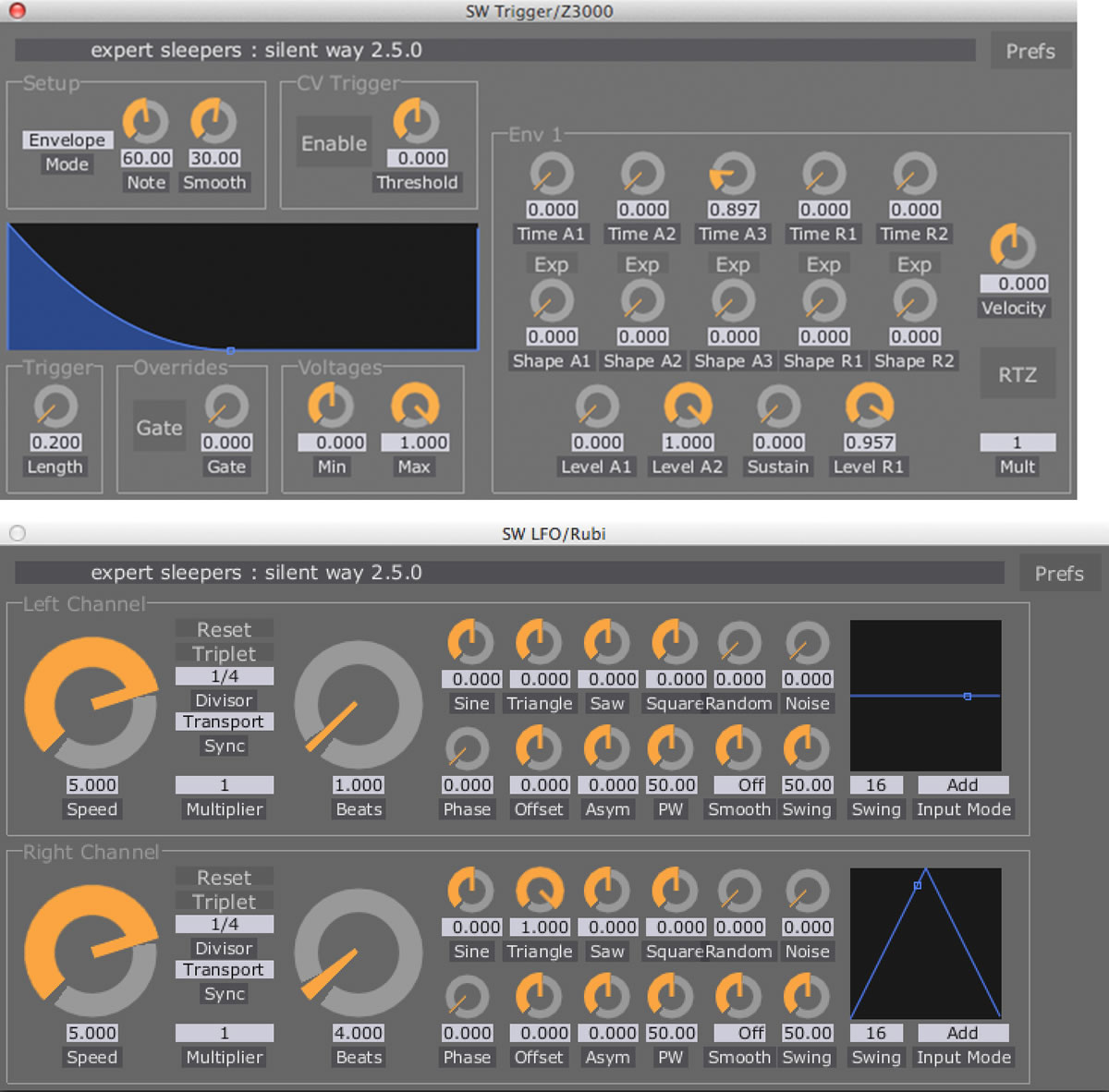
This plethora of ins and outs is driven by a rather large Ableton Live session. This contains no audio clips, but 36 audio channels (and eight MIDI channels, used to allow the integration of external controllers). Most of these host Max for Live and Silent Way plug-ins. The Silent Way plugins (Fig. 7) are used for very full-featured LFOs and envelopes. The Max for Live ones (Fig. 8) are very simple — they are simply hosts for MIDI automation, which is essentially translated into OSC to be sent to a separate Max patch. My original plan was to build the entire system in Max for Live, but this didn’t work too well — the DSP load was very irregular, and the audio frequently disrupted. For some reason, the Live / Max for Live / Max combination runs much more smoothly, even though the actual patching is the same. This is a rather unsatisfactory compromise, but it works.
A Certain Ratio
As mentioned above, I wanted to build a synthesizer that was not built on equal temperament. I’ve long been fascinated by the harmonic series, which I’ve used overtly (of course, it’s kind of hard to avoid) in my work throughout my career and so decided to implement tunings derived from natural low-order harmonic ratios into the system.
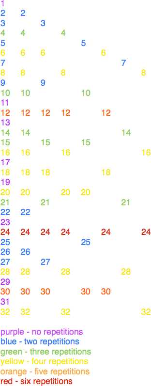
Fundamental to the design of the system is a process of “harmonic stacking”, which is something I have used time and time again in my music. It’s very simple: it involves building a harmonic series on every degree of a harmonic series. In the digital domain I’ve done this primarily with comb filters — this was the basis of the system used in Vanishing Point, mentioned above. In its simplest form, this might initially appear as a somewhat pointless process: a harmonic of a harmonic will always sit somewhere on the harmonic series of the original fundamental, so stacking harmonic series in this way will not actually produce any new harmonics. However, interesting patterns will appear, with “nodes” of repetition appearing in the harmonic series that emphasise certain harmonics above others (Fig. 8). When the process is carried on far up the harmonic series (beyond what is shown in Fig. 8), it functions to essentially counteract the exponential nature of the harmonic series (the harmonics getting perceptually closer together the higher up the series you go). This is because the nodes of repetition actually get farther apart. Carried on across the whole frequency range, it results in something close to a “chord” of roughly evenly spaced intervals that is aurally rather pleasing.
In actual usage, I often vary this model so that the relationship of the harmonic series “stack” to the original fundamental is more complex than that outlined above. This usually uses a process of reciprocity (as often discussed in derivations of just-tempered scales and tonality), where the secondary harmonic series are built not on their respective fundamental but rather an implied subharmonic. A variety of more complex harmonic structures can be built in this way — if the reciprocal relationships are reasonably simple, they will still sound fairly harmonic, but increasing the order of reciprocity is an easy, measurable and modulate-able control of perceptual dissonance.
It occurred to me early on that achieving harmonic stacking in my synthesizer would be relatively easy. This is at the heart of my decision to primarily use sawtooth waves. Since these produce a strong harmonic series, arranging them on a harmonic series themselves would do just that. At first sight, it may seem as though my synthesizer is built on a classic “West Coast” subtractive synthesis model (harmonically-rich oscillator→filter→VCA), but the aim is rather different. The filter is used in a specific way — closely controlled using the Silent Way system — to hone in on specific harmonics at any position in the harmonic stack. It should also be noted that four of my voices incorporate wavefolders, which, when applied to sawtooth waves, allows a third order of harmonic stacking (harmonic series on harmonic series on harmonic series).
Tuning In

It rapidly became apparent that if I was going to work with pure harmonic ratios, especially polyphonically, I needed the synthesizer to be absolutely in tune. One of the ironies of working with these intervals is that to Western ears, conditioned by a lifetime exposure to equal tempered music, they can sound exotic or even discordant. With this in mind, I have found it important to have the courage of my convictions — when using the seventh harmonic, a particularly eye-watering example (heard by Western ears as a very flat minor seventh), it needs to be just so. There’s a huge amount of difference between an interval a few cents off and one that’s exactly in tune. If it’s in tune, and played with some more “straightforward” even harmonics, the beats and resonances that are set up between the intervals anchor the more unfamiliar harmonic and convince the ear of its harmonicity.
Attempting this degree of tuning accuracy with analogue oscillators is tilting at windmills — absolutely a non-trivial problem, and arguably impossible. Getting eight oscillators in tune for a single set of intervals is difficult enough: my ear is (regrettably) not really good enough, so I have used a series of tuners for this. Initially I used software — the Aglaë Software Tune It! plug-in provided a simple shareware solution. However, it rapidly became clear that tuning the synth this way was cumbersome and time-consuming. Hardware proved a better solution — I found that Snark guitar tuners, cheaply and easily available on eBay, can be “hacked” to have a minijack input in place of the internal microphone, and plugging these directly into the oscillators provided a much quicker way of tuning up (Fig. 9). This works well, but it still takes time (not really something that can be done in the middle of a performance), and a tuning process using this method will still only tune the oscillators for a single note apiece.
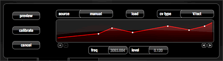
One of the problems of using analogue oscillators in a pitch-critical scenario is that the tracking of such oscillators is never 100 percent accurate. “Tracking” is the term used to describe the behaviour of the oscillator in terms of the pitch produced in response to CV voltages. Most Eurorack oscillators (and certainly all of mine) operate according to a 1 volt per octave (1V/oct) system, whereby a 1-volt increase to the pitch CV input will result in an octave increase in pitch output (or a doubling of frequency). Of course, this is never entirely accurate. This response needs to be calibrated: with most oscillators this involves a single trimmer to adjust the ratio between CV voltage input and frequency output, but with others it involves several. However, in all cases the response arrived at is a compromise, with inconsistencies and non-linearities across the frequency range. There are ways to compensate for this, and they involve a more complex calibration process, usually using software: Silent Way itself provides this function, and a slightly more sophisticated version is provided by MOTU’s Volta plugin. A hardware implementation (but using a similar, DSP-based algorithm) can be found in Vince Clarke’s VCM and VCS modules. All three involve roughly the same procedure: the software/hardware carrying out the tuning and calibration (hereafter referred to as the calibrator) is connected to the 1V/oct input of the oscillator and the output of the oscillator (an untreated, simple waveform — sine or square seem to work the best) fed back into the calibrator. The calibrator then produces a series of voltages corresponding to expected frequencies across the full range of the oscillator. The frequency produced by each of these voltages is measured using a pitch-detection algorithm, and this frequency is compared with the one expected. From the relationship between these, a graph is produced which will effectively allow the calibrator to compensate for the inconsistencies of the oscillators tracking. As can be seen in the example shown in (Fig. 10), these inconsistencies are often not inconsiderable.
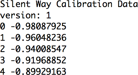
I spent some time working with both the Silent Way and Volta calibration systems. These come a long way towards facilitating a perfectly in-tune analogue oscillator, but they have certain shortcomings, at least for my purposes. The first is that they are built for equal-tempered chromaticism, which means that I would either need to repurpose the data produced by the calibration for my own model, or to modify the calibration software for my own purposes. This is to some extent possible with the Silent Way software, where the calibration data is a text file (Fig. 11). The format of this editable text file is very simple, consisting of pairs of numbers, the first being a MIDI note value and the second the corresponding text value.
However, this is somewhat cumbersome in practice, and I also felt I needed to address another shortcoming. Although the calibration provided by these methods is very accurate, the process takes time. Only a few seconds, but — given that it also involves making the oscillator produce an arbitrary set of pitches — enough that it would be undesirable during a performance.
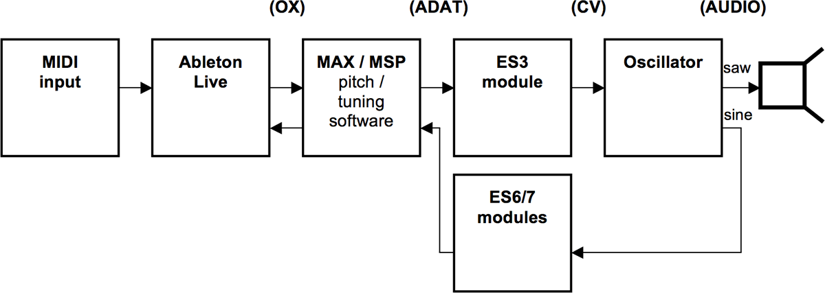
This brings me to the other challenge in seeking perfect tuning with analogue oscillators: that their pitch will often drift slightly over time. With this in mind, I set out to build a system that could effectively carry out calibration on a continuous basis. 1[1. I’m not the only person to attempt something of this nature. PA Tremblay, for example, uses similar techniques with his modular synthesizer, and indeed gave me some useful pointers here.] This essentially follows the same methodology as the systems mentioned above, but rather than using an arbitrary set of pitches it uses the actual pitches required by the composer/performer at any given time. This proves to be a complex process. Each of the oscillators needs to be under constant CV control by the software (this was already built into my system). In addition, the software requires access to the output of each oscillator. This needs to be untreated if possible, so an additional feed from that used for the (sounding) audio output is required. Since the saw outputs of the eight oscillators are used for the audible output, the sine outputs are used for the tuning/calibration by being fed into the software (Fig. 12). The frequency of each is tracked — I explored a wide variety of techniques for doing this, but eventually found the [sigmund~] object, developed by Miller Puckette and available within Max/MSP and PD, to be the most effective. Under certain circumstances, alternative methods using [fiddle~], [analyzer~] and various descriptors objects worked well, but where [sigmund~] won out was in tracking low frequencies — the other methods become unreliable with frequencies much below 100 Hz.
The Max patch I finally used in the system for the tuning/calibration derives the expected frequency from each harmonic as it is played, using the expression [expr(pow(2., $f1)]. This frequency is then compared with the actual frequency being produced by the oscillator. What happens next required many iterations before I got it right: my first approach was the obvious one — I simply divided the expected frequency by the actual one and then multiplied the CV signal by this amount. However, this proved to be laughably ineffective in practice. This is a factor of the inherent latency of the system combined with the instability of analogue oscillators. By the time the software has made an adjustment, the frequency of the oscillator being adjusted has changed slightly. This results in the system “chasing its tail” and wobbling hopelessly and ever more inaccurately around the required pitch — quite an interesting effect actually. I spent a long time tweaking this system to try and compensate for these shortcomings, before abandoning it for a rather crude approach, which closely mimics how a human might tune an instrument. Rather than try to work out the difference between the expected and actual frequencies and therefore to implement a single adjustment, I went for an iterative approach. What the system does is essentially simply measure whether the actual frequency is more or less than the expected one. If it’s more, then the frequency is adjusted a tiny bit downwards; if less, a tiny bit upwards. The process is then repeated until the two frequencies are equal.

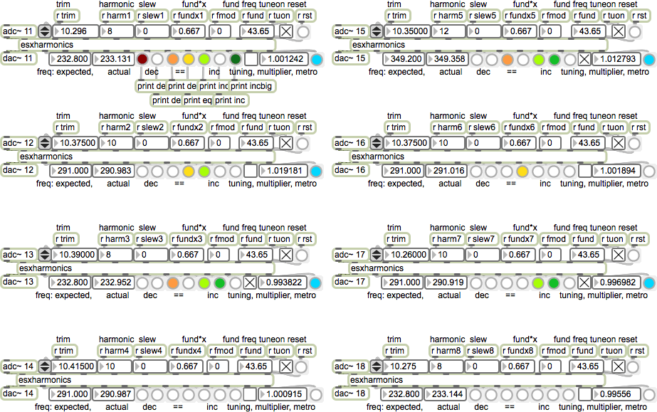
This method has been refined a fair bit since I first built it, mainly to make it more efficient and to speed up the process. The [esxharmonics] abstractions found in the tuner patch as it stands (Fig. 13) contain something similar to the patch shown in Figure 14. The main development has been multiple levels of adjustment, so that the system makes a coarse adjustment first, then a fine one, then a super-fine one. I’ve also had to build a certain amount of tolerance into the system — even though this method is more forgiving than my first approach, I’ve still found that trying to tune the oscillator to an exact frequency produces the kind of constant “wobbling” I was trying to avoid (albeit of a much less extreme variety to that described above). A better approach is to specify a narrow band around the required frequency as “good enough”, and stop the tuning process once this band is hit. This is a compromise, but it provides a tuning accuracy of ±0.01%, which is good enough for my ears. The tuning is not instantaneous using this method — in most cases it takes less than 100 ms, which in practice is negligible, especially as the adjustments are usually quite small. However, in extreme cases — in particular with a large intervallic leap and/or where the calibration of the oscillator is a little off — it can take up to a second for the tuning to lock in. Whilst this is a flaw, I’ve decided I quite like it. There is indeed something rather human-sounding about the tuning process. The occasional momentary drift provides some interesting colour, and the process of honing in on the correct pitch is rather pleasing. I have even started to find ways of tricking the system to make these hiccups occur more often — the irony of this is not lost on me.
Shortcomings
Notwithstanding the self-justification above, I do believe there are shortcomings in my tuning system and intend to explore further refinements or indeed fundamental changes to this system in future. The main issue is with efficiency — the system is incredibly processor intensive as it stands. The [sigmund~] object is very demanding, especially with the large window sizes required to track across the full frequency range. Eight of them will use up the CPU cycles of an entire processor core on my MacBook Pro. A phase vocoder-derived method of pitch tracking seems overkill in a situation where the pitch being tracked is a simple sine wave. Alternative methods that have been suggested to me are something akin to a strobe tuner or some kind of heterodyning — in both cases combining the analogue waveform with a “perfect” digital copy produced by the software to measure the difference. It also occurs to me that some kind of unorthodox low-level solution might be possible using square waves rather than sines and essentially treating them as clocks (and comparing with a computer-generated square wave as a digital clock). This would be somewhat akin to the process used in 1980s DCO designs, but different in that the actual sound produced from the oscillator would not be derived from the clock pulse itself (although this might be something to explore!).
Despite a lot of work and numerous compromises, Ableton Live is not serving me well as my host. It seemed ideal for this purpose, since everything could be built in Max for Live. However, as mentioned above, the pitch/tuning engine of my software — by far the most demanding part — is now running in regular Max, with Live communicating with it over OSC. Despite this, Live still tends to glitch the audio from time to time — at the very highest buffer size this is minimized, but this of course results in very high latency. I intend to rebuild the system from the ground up entirely in Max (probably also replacing the Silent Way plugins — although I find them very useful, I think the integration of everything in a bespoke Max environment would open up some new possibilities).
Yes, but What Does It Sound Like?
I feel like I’m still at an early stage in terms of making music with my modular synthesizer. Although I’ve been developing the system for over a year now, it’s only recently that it has come together into something approaching my original vision for it. I’m still some way off a coherent composition or performance, but over the last few months I’ve been experimenting with it quite a lot and starting to generate some material, some of which I can share here. None of this should be heard as “finished” music, but it functions reasonably well as a demo to illustrate what the synth sounds like. Of course, all of this is originally in eight channels — these are rather rough and ready stereo mixdowns that give a very different impression to the octophonic versions. Note there’s some reverb and delays applied — these are a mixture of analogue (Electro-Harmonix Deluxe Memory Man and Donner Yellow Fall guitar pedals, Music Thing Modular Spring reverb module) and digital (2C-Audio Aether reverb plugin). There’s minimal editing here and there (to cut down extended sequences), but no other processing or post-production.
Looking Ahead
I’m very happy with the sonorities I’ve got coming out of my super-tuned synthesizer. To me, the locked-in intervals really sing. They tend to sit together so nicely that they perceptually form a single rich timbre — quite interesting when the various partials are distributed around eight speakers. This is somewhat ironic, in that I am starting to think of the synthesizer more as a unified instrument after all.
So far I’m getting some really nice drones out of the synth. However, I must say that on a temporal microscale — thinking about detailed gestures or rhythms — it leaves something to be desired. I think this is partly a usability issue (I haven’t yet arrived at a very elegant user interface for controlling eight voices at once, despite experimenting with a variety of MIDI and other controllers) and partly a fundamental problem with the system. As mentioned above, I’m currently experiencing rather major latency issues, but if I take steps to remedy the latency (i.e. use smaller buffer sizes) then the audio quality is affected. However, even if I do minimize buffer sizes etc., I’m finding the system isn’t very “snappy”. Perhaps digitally generated CVs don’t move quite fast enough, or the VCAs in the A-135-1s aren’t the best, but rhythmic material just doesn’t punch through.
I think using computer-made CV signals has opened up a great many possibilities, and I’m happy with what I’ve achieved. However, I have started to realize that I might have missed out on some of the pleasures afforded by modular synthesizers by delegating my CV duties to my computer. In fact, whilst I do not regret my decision to keep the computer as part of my workflow (I do not think the system as it stands would be possible without it), I’ve more and more wanted to get away from the computer, at least some of the time, and work purely with the modular.
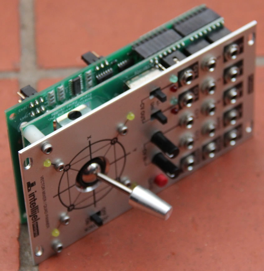
With all of this in mind, I’ve started to build another, smaller system (Fig. 15) designed to complement the first and be used alongside it. This system is also designed for 8-channel playback, but following a different model. The first is “parallel” — mainly I’m operating with one voice assigned to each speaker, allowing a rich immersive sound space, but little by way of movement. The new system is “serial”, and operates somewhat akin to an old-school BEAST-style sound diffusion system, where a stereo source is distributed between many loudspeakers. Here there are indeed two channels of sound distributed between the eight speakers, with two Intellijel Planar quad panner modules (Fig. 16) being used to move the sounds around, either manually using the modules’ beautiful joysticks or under CV control. The sound sources I’m using are very different to the first system — no traditional oscillators or filters — and are designed primarily for percussive, pitch-agnostic sounds and gestures. Crucially, a large proportion of the modules — such as a Make Noise Maths and an MMS Pingable Envelope Generator — are designed specifically for complex CV generation and modulation. In general, I’m going for a quirky, DIY æsthetic with this one. I’m using non-modular elements — guitar pedals and the like — and many of the modules I’m using are self-built. To date this has largely been from kits, but I’m starting to design a couple of my own.
Whilst, as mentioned above, I am keen to explore other methods of tuning than the rather crude iterative process I’ve built using [sigmund~], I have come to enjoy the actual audible tuning process and am interested in building future works entirely around this as a creative feature. One of the things I find exciting about my tuning method is precisely the fact that it’s crude and relies simply on nudging the pitch up if it’s too low or down if it’s too high. This means that it can essentially be applied to anything. In the modular world, it makes it easy to tune modules that aren’t designed to be tuned — whilst some self-resonating filters provide 1V/oct pitch control, for example, many do not. My tuning system can tune them perfectly anyway. There are many complex processes that produce pitched tones — many kinds of feedback for example. These are by their nature non-linear and unpredictable. However, provided they have at least a small amount of replicability (“turn this knob counter-clockwise and the pitch goes up, turn it clockwise and it goes down”), my system can tune them.
I’m looking further beyond that to electromechanical applications of the same process. I’ve already built an Arduino-connected stepper motor which will simply step up or down in response to a tuning measurement. At the moment I’m experimenting with an old shortwave ham radio and heterodyning “whistles”, a favourite sound source of mine. These exhibit precisely the non-linear but predictable-over-short-distances behaviour mentioned above, and seem to be essentially “tuneable” using this system. 3[3. You may wonder why on earth I’m using a stepper motor to do this rather than an electronic method — since the tuning dial is a variable capacitor rather than a resistor, such an electronic method is non-facile, and I’ve actually found several existing systems for automating radio tuning using stepper motors, albeit designed for less outré purposes.] Looking further ahead it would be possible to tune a string this way, or — with a bit of imagination — most instruments or mechanical devices that are capable of producing pitch.
A Visual Dimension

As mentioned in the introduction, I have a strong and abiding interest in audiovisual work. One of the motivations I had in immersing myself in modular synthesis was a feeling that I needed to spend some time purely in the audio domain, developing something new (to me) without recourse to the distracting excitement of the audiovisual. To some extent this has been successful — I’ve certainly spent more critical listening time with my modular than I have with anything for a long time. However, somewhat to my chagrin, I haven’t been able to resist extending some of these ideas into the audiovisual domain.
There’s a strong community of people working with analogue modular video synthesizers, and this would be an obvious area for me to move into if I wanted to explore some of these ideas visually. However, I’ve not had too much trouble resisting this so far. One of the unspoken aspects of modular synthesizers is that they’re — terrifyingly — expensive. Video synthesis modules are particularly complex and therefore often even more expensive than audio ones. I know that I simply can’t countenance the idea of building up a modular video system alongside my audio one. I have dipped my toes in these waters by building a small standalone video synthesizer, Gijs Gieskes’ wonderfully-designed and gnomically named 3TrinsRGB+1 (Fig. 17). I should say in passing that this was one of the first things I built, buoyed up after a workshop with Tom Bugs at the Sines and Squares festival in Manchester in October 2014 — where I did a performance with an early version of the system outlined here, albeit without the tuning system — and it’s been by far the hardest. After that baptism of fire most module kits have seemed relatively easy.

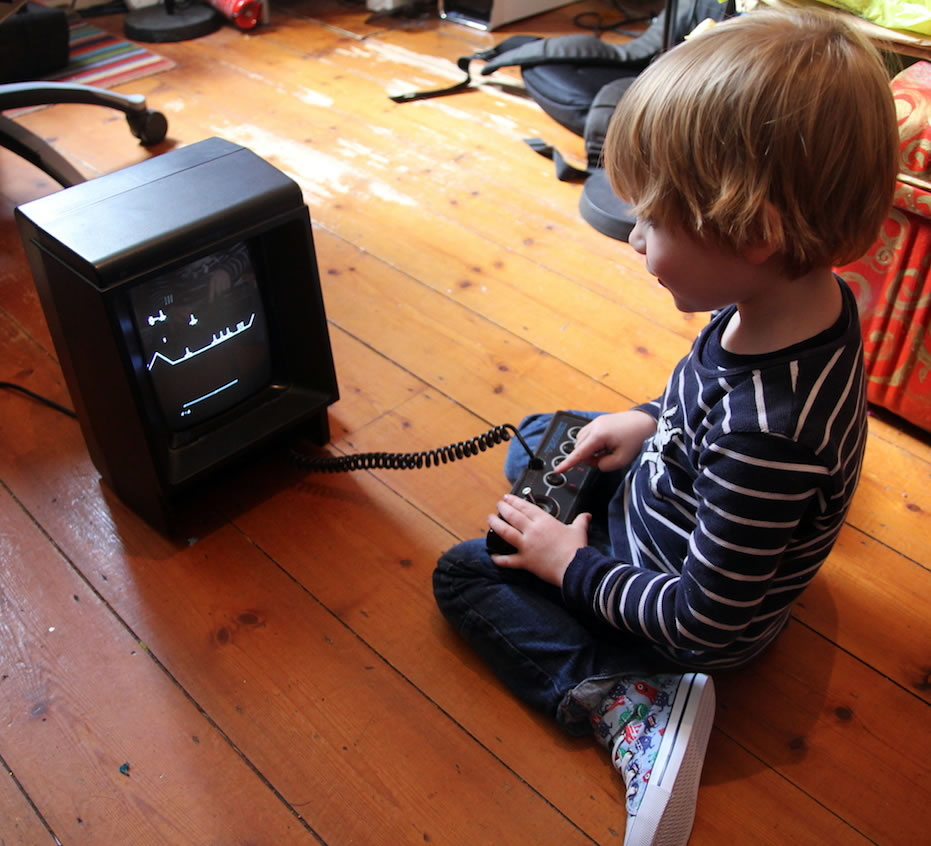
However, what I’ve become particularly interested in is vector graphics, of the sort produced by an old analogue oscilloscope. This interest was also engendered at Sines and Squares. Here I saw Andrew Duff demonstrate a hacked MB Vectrex, a somewhat ill-fated 1980s domestic games console based around a vector monitor (Fig. 18), as a kind of home-made oscilloscope — technically crude, but æsthetically extremely pleasing. I was immediately obsessed with the thing, and pestered Andrew until he talked me through hacking one of my own. Since then I have hacked several more, and have also become an avid eBay collector of old oscilloscopes. So far my top find has been a Wavetek 1910C, a specialist XY vector monitor which has a huge 12-inch screen (Fig. 19).

With these, I’ve been exploring in particular Lissajous figures, where both the x and y axis (and indeed the z axis — brightness) are controlled by audio signals. These provide a beautiful way of visualizing the sort of harmonic relationships I’m working with, where the low-order ratios between pitches produce satisfyingly coherent geometries. Here I have again found a promising use for a hybrid analogue/digital approach. I have built a Max patch that takes three waveforms from the analogue synthesizer and converts them from Cartesian to Polar coordinate space. This produces an array of circular, spiral and related forms (Fig. 20) that I found both attractive and very reminiscent of the work of motion-graphics pioneer John Whitney. Further research, in particular a close reading of his book Digital Harmony (1981) has revealed that this is no coincidence, and that his algorithms are very close to what I am doing, albeit arrived at by a very different route. I intend to produce an audiovisual work that exploits this discovery as an overt homage to Whitney and his ideas.
Bibliography
Expert Sleepers. http://www.expert-sleepers.co.uk
Fantinatto, Robert (Dir.). I Dream of Wires: The resurgence of the modular synthesizer. 2014.
Hyde, Joseph. Zoetrope (1998). Vimeo video “Zoetrope — part 1” (5:08) http://vimeo.com/1664479 and “Zoetrope — part 2” (8:55) http://vimeo.com/1664232 posted by “Joseph Hyde” on 6 September 2008.
_____. End Transmission (2009). Vimeo video “End Transmission” (10:05) posted by “Joseph Hyde” on 16 February 2009. http://vimeo.com/3241660
ModularGrid: Patching Things Together. http://www.modulargrid.net
Muffwiggler forum. http://muffwiggler.com/forum
Whitney, John. Digital Harmony: On the complementarity of music and visual art. New York: McGraw-Hill Inc., 1981.
Social top